
Introduction
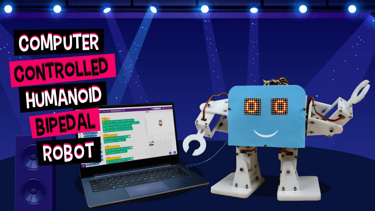
Casper was the first DIY humanoid robot that we built. But all it could do was speak with its eyes and it moved around on wheels. Today, we’re to build another humanoid robot that is not only as expressive as Casper but can also dance, move around, and give you a hi-5 among other things! And it’s super cute! All the components that you need to make it are available in the Humanoid Robot Kit and you can easily program it in PictoBlox, our smart graphical programming software. You can download it from HERE.
Hop on board ‘cause we’re beginning in 3, 2, 1… now!
Assembling the Base of the Humanoid Robot
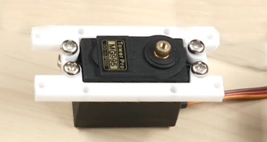
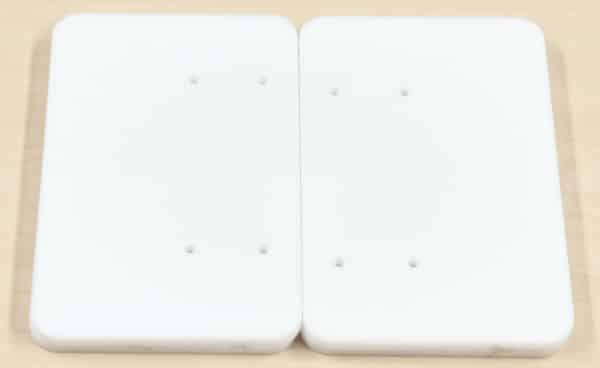
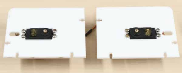
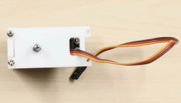
Let’s start the assembly by making the base as to this all the rest of the body parts will be attached. Take the body base plate and attach two metal servos to the space given using M4 bolts and nuts. One for the left leg and another for the right leg.

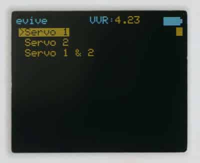
Calibration of the servo has never been this easy. Connect the metal servo to either of the Servo Channel. Switch ON evive, you notice a menu on the TFT Screen, this is evive’s firmware. Select Controls, Select Servos, then select Servo channel on which the servo is connected. Then, using the corresponding potentiometer set the servo angle to 90°.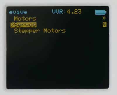
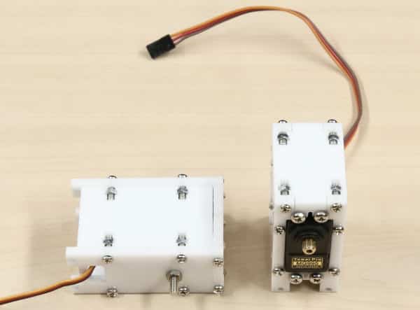
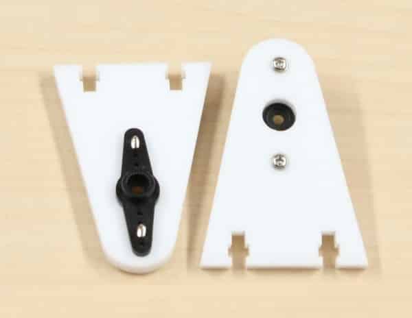
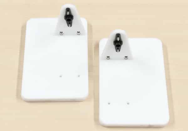
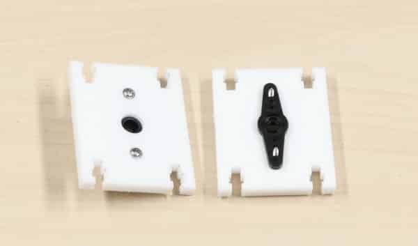
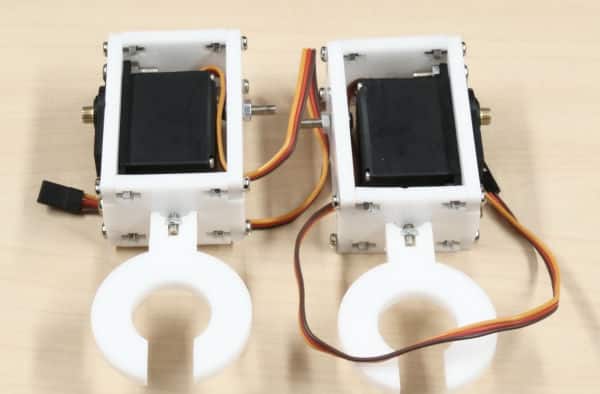
Once done, take the leg servo horn plates and attach the two-sided servo horn to it using servo screws(which are already available in the servo accessories). 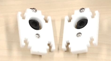
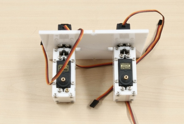
Now attach the leg servo horn plates to the body base plate by mounting the servo horns to the servo heads using servo bolts.
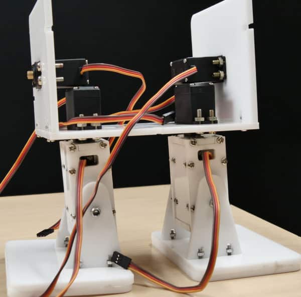
Assembling the Legs
Now, let’s start the assembly of the leg.
- Take the leg back servo plate and attach a metal servo to it using M4 nuts and bolts.
- Next, take the leg side plates and attach them to the leg back servo plate using M3 bolts of length 12mm and M3 nuts.
- Next, take the leg bottom plate and attach it to the leg side plates using M3 bolts of length 12mm and M3 nuts.
- Then, take the leg front plate and screw M4 bolt and nuts to it in the hole given in the center.
- Now, fix this leg front plate to the leg side plates using M3 bolts of length 12mm and M3 nuts. Make sure that the slot given for the wire to pass is close to the body base plate.
- Repeat steps 1 to 4 for the other leg
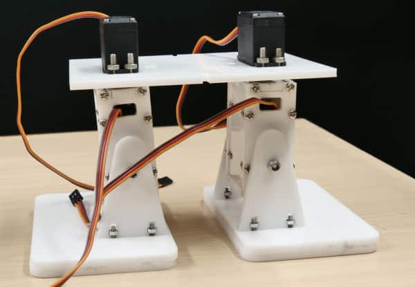
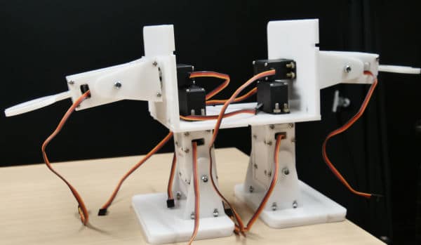
- Once both the leg-sub assemblies are ready, fix them to the leg servo horn plate by using four M3 nuts and bolts.
With this, the leg assembly of our bipedal is complete. Let’s move forward to the making of feet of the bipedal.
Assembling the Feet of the Bipedal
Let’s begin with the feet assembly.
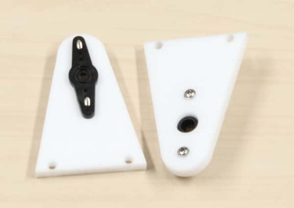
- Take the foot base and glue it to the foot sole. Keep it aside to dry.
- Till then, take the foot servo horn plate and attach two-sided servo horn to it using servo screws.
- Next, place the servo horn plate and foot front plate on the foot base and attach it using M3 bolts of 12mm length and M3 nuts.
- Repeat steps 1 to 3 for the other side of the foot too.
- Finally, we are going to fix the feet assemblies to the leg assembly by attaching the servo horn on the servo using servo screws. And fix the foot front plate to the leg assembly using M4 bolts and M4 locknuts. This will give movement to the feet of the robot.
Phew! The lower body of our humanoid is complete. It’s time to make the upper body.
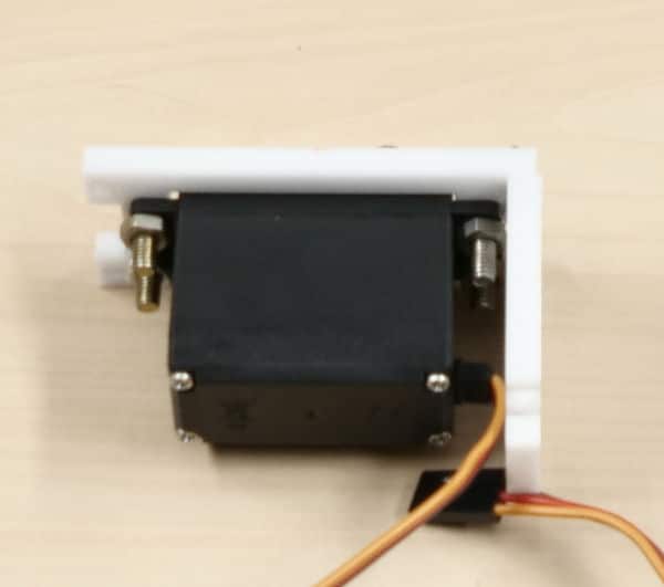
Assembling the Shoulders of the Robot
Let’s start the assembly of the shoulder.
- Take one of the body side plates and attach a metal servo to it using M4 bolts and nuts.
- Once done, attach that body side plate to the body base plate using M3 bolts of 12mm length and M3 nuts. Make sure that you fix the side plate in such a way that the servo head points outwards.
- Now, take the shoulder servo horn plate and attach the double-sided horn to it using a servo screw.
- Finally, attach the servo horn of the shoulder servo horn plate to the servo head on the body side plate using servo bolt. This allows the movement of the entire hands of the robot.
- Repeat the above steps for the other side of the bipedal.
Assembling the Hands
Let’s begin the assembly of the arm.
- Firstly, take the arm back servo plate and attach the servo horn to it using M4 nuts and bolts.
- Then, attach the arm bottom plate to the arm back servo plate using M3 bolts of 12mm length and M3 nuts.
- Screw M4 bolt and M4 lock nut into the hole given in the middle of the arm bottom plate.
- Next, attach the arm front plate to the arm bottom plate using M3 bolts of length 12mm and M3 nuts.
- Then, screw the claw on the arm top plate using M3 bolts of 12mm length and M3 nuts.
- Fix the arm top plate to the arm back servo and arm front plate using M3 bolts of 12mm and M3 nuts.
- Next, take the shoulder back plate and attach the servo horn to it using a servo screw.
-
- Once the arm assemblies of both the sides are completed, fix them on the body side plate by fixing the servo horn on the shoulder servo horn plate to the servo head.
- Attach the shoulder front plate to the arm back servo plate using M4 bolts and M4 lock nut and to the shoulder servo horn plate using M3 nuts and bolts of 12 mm length.
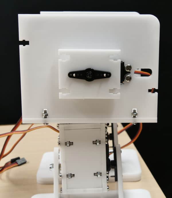
Giving the Face to the Robot
Now, that the arm is attached, let’s attach the face to our bipedal robot.
Attach the body front plate to the body base plate and the side plates using M3 bolts of 12mm and M3 bolts.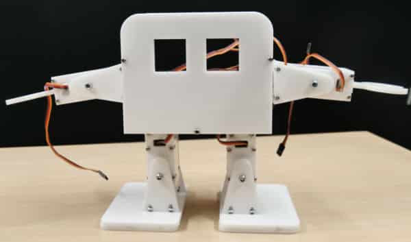
Assembling the Back
Finally, attach the body back plate to the body base plate and the side plates using M3 bolts of 12mm and M3 bolts.
Giving Vision to the Robot
We will be using two 8 * 8 LED Dot Matrices as the eyes of our robot. It will express different emotions through its eyes. Let’s connect both the LED matrices to evive as given below:
- Left Dot Matrix:
- CS: 10 of evive
- CLK: 11 of evive
- DIN: 12 of evive
- VCC: 5V of evive
- GND: GND of evive
- Right Dot Matrix:
- CS: 22 of evive
- CLK: 23 of evive
- DIN: 24 of evive
- VCC: 5V of evive
- GND: GND of evive
Once connections are done, fix the matrices into the hole given on the body front plate.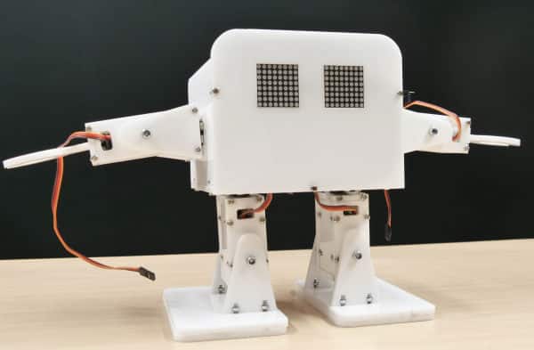
Making the Robot Capable of Movement
Make the connections as given below: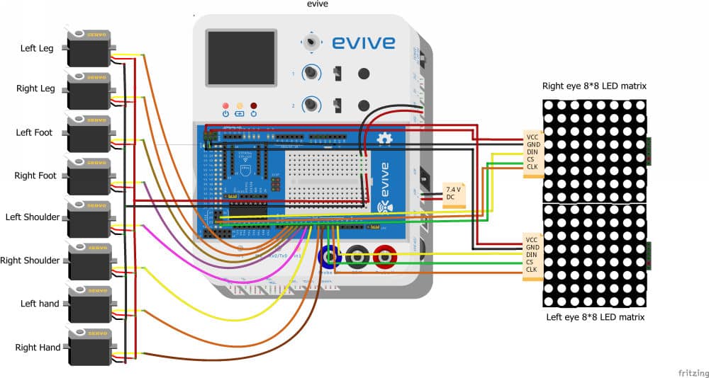
- Left leg servo:
- VCC (Red wire): 5V of evive
- GND (Brown wire): GND of evive
- Signal (Orange wire): Digital pin 2 of evive
- Right leg servo:
- VCC (Red wire): 5V of evive
- GND (Brown wire): GND of evive
- Signal (Orange wire): Digital pin 3 of evive
- Left foot servo:
- VCC (Red wire): 5V of evive
- GND (Brown wire): GND of evive
- Signal (Orange wire): Digital pin 4 of evive
- Right foot servo:
- VCC (Red wire): 5V of evive
- GND (Brown wire): GND of evive
- Signal (Orange wire): Digital pin 5 of evive
- Left shoulder servo:
- VCC (Red wire): 5V of evive
- GND (Brown wire): GND of evive
- Signal (Orange wire): Digital pin 6 of evive
- Right shoulder servo:
- VCC (Red wire): 5V of evive
- GND (Brown wire): GND of evive
- Signal (Orange wire): Digital pin 7 of evive
- Left-arm servo:
- VCC (Red wire): 5V of evive
- GND (Brown wire): GND of evive
- Signal (Orange wire): Digital pin 8 of evive
- Right-arm servo:
- VCC (Red wire): 5V of evive
- GND (Brown wire): GND of evive
- Signal (Orange wire): Digital pin 9 of evive
Looking into the System
The bipedal robot is the cutest and the most entertaining robot works completing on the basis of servos. The eight servos are used for the movement of the bipedal and the LED dot matrix, draws the expression on the display.
The lower body of the robot contains four servos in total, two for the movement of feet and two for the movement of the entire leg. We can easily code them with the help of the code given in the below step. Which can make the robot, walk, dance, turn, bend, etc.
The upper body contains six… no seven major components. Two servos are used for the movement of the claw. The other two for the movement of the entire hand assembly. Which let the robot do the movement of fly, say hi, or a shake-hand. The two LED dot matrics for the display of emotions like a wink, looking left or right, falling in love, and many.
We have assigned some basic functions to the keys of our computer, you can change the function if you want.
Controls:
- Up Arrow: Walk forward
- Down Arrow: Walk backward
- Right Arrow: Turn right
- Left Arrow: Turn left
- w: Robot will do Hands-up
- s: Robot will straighten the hands
- a: Robot will give a HI-FIVE from the left hand
- d: Robot will do a handshake from the right hand
Making the Humanoid Computer Controlled
Coding the bipedal humanoid robot has never been this easy. Secret? PictoBlox. We will code the bipedal in PictoBlox- a graphical programming software. Where we can just drag and drop the blocks and the code is ready.
The best part? We can calibrate the servos in real-time.

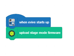
Follow the steps given here to calibrate your humanoid robot:
- Before we start working with the bipedal, the first thing we need to do is upload the firmware. Upload the following code to upload the firmware:
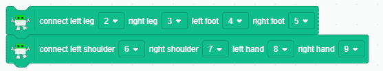
- Using the connect left leg () right leg () left foot () right foot () and connect left shoulder () right shoulder () left hand () right () blocks, we will first define the PWM pins off all the servos:
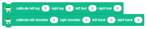
- To calibrate the Legs and Shoulders Servos use calibrate left leg () right leg () left foot () right foot () for legs and calibrate left shoulder () right shoulder () left hand () right hand () for hands block. Enter the error angles in the spaces given.
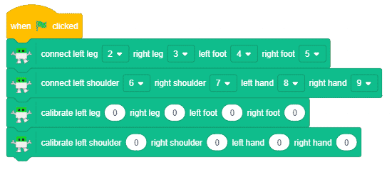
- Write the script given below to calibrate your robot:
Once everything is done, write the following code to control your robot using your computer: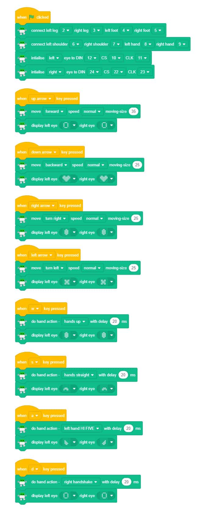

Other Ways to Calibrate your Humanoid
If you are unaware of the error angle or you want to know at which angles do the robot’s legs and and feet are straight, write the code written below:
To know the error angle of leg servos:
Once you run the script given below, you’ll be able to use the potentiometer 1 and potentiometer 2 to visually calibrate the angle. The potentiometer values are being displayed on the stage which further can be used as the error angle in the calibration block.
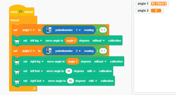
Similarly, you can calibrate the feet servos too.
Conclusion
With this, your DIY humanoid robot is ready. Have fun with your robo-pal!


![[CODEAVOUR 2021] project demonstration video 4-12 screenshot](https://ai.thestempedia.com/wp-content/uploads/elementor/thumbs/CODEAVOUR-2021-project-demonstration-video-4-12-screenshot-q7ynxvlwjfsgj74xjev4cqopqur232if4hglkl3itk.png "[CODEAVOUR 2021] project demonstration video 4-12 screenshot")


