Introduction
We are going to follow the steps in this lesson to assemble the Pick and Place Quarky Mecanum Wheel Robot.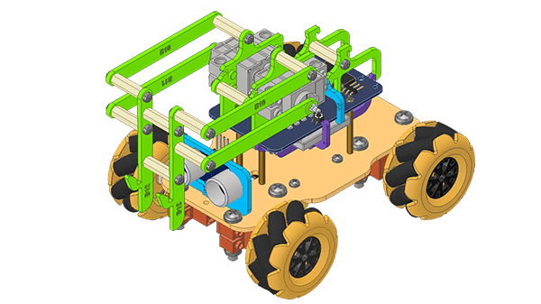
Assembly Steps
We will be starting the assembly of the Basic Quarky Mecanum Wheel Robot.
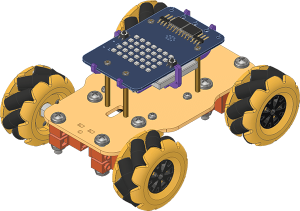
If you haven’t had your robot assembled till now, please follow this tutorial and then continue: https://ai.thestempedia.com/docs/quarky-mechanum-documentation/assembling-basic-quarky-mecanum-wheel-robot/
Once completed, follow the steps:
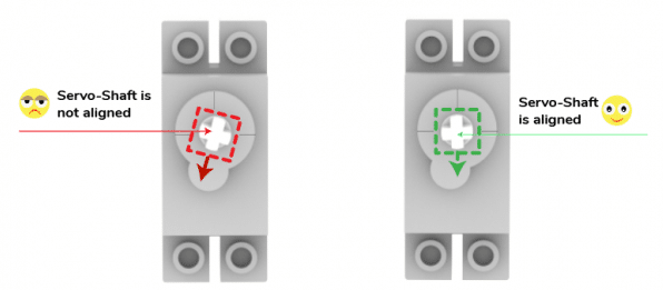
- Calibrating the Servo Motor: First we need to calibrate the servo motors, i.e., we need to first both the servos to 90 degrees. This will ensure that the angle of each servo motor is properly aligned. Follow the steps:
- Connect the first servo motor to the first Quarky Servo Connector, ensuring that the brown wire is on the left side.
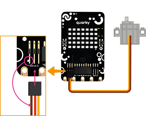
- Connect Quarky to your laptop using a USB cable.
- Open PictoBlox on your desktop. After that, select Block Coding as your coding environment.

- Then, click the Board button in the toolbar and select board as Quarky.

- Next, select the appropriate Serial port if the Quarky is connected via USB or the Bluetooth Port if you want to connect Quarky via Bluetooth and press Connect.

- Quarky is now connected to PictoBlox. Create the following script:
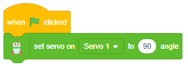
- Click on the green flag over the stage to run the script. You will find that the servo motor shaft gets perfectly aligned.
- Remove the servo motor from Quarky. Connect the other servo motor and calibrate.
- Connect the first servo motor to the first Quarky Servo Connector, ensuring that the brown wire is on the left side.
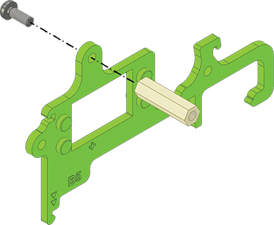
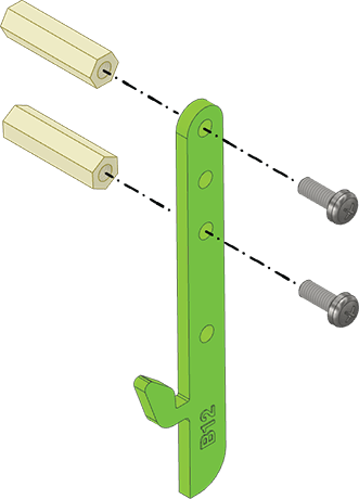
- Fix two M3 Spacers (20mm) on the B5 Green Part with M3 Bolts (8mm).
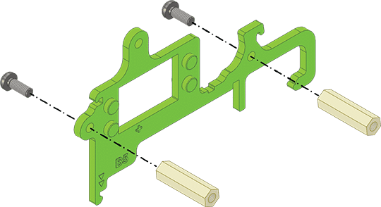
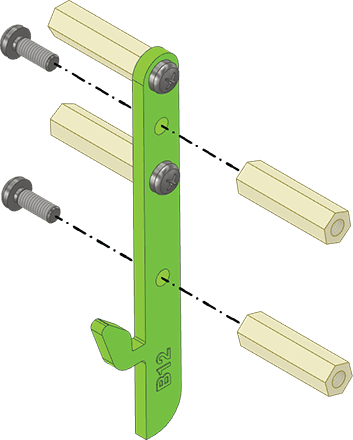
- Fix another M3 Spacer (20mm) on the opposite side of the same B5 Green Part with M3 Bolt (8mm).
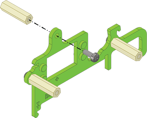
- Fix another M3 Spacer (20mm) on top of the other B5 Green Part with an M3 Bolt (8mm).
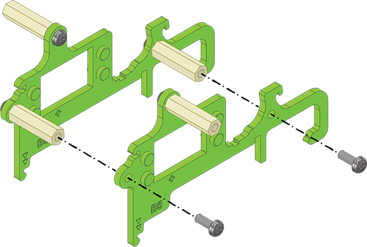
- Align both the B5 Green Parts on M3 Spacers (20mm) as shown below and fix them using two M3 Bolts (8mm).
- Snap the 180° Servo Motors to the B5 Green Parts such that their shafts align with the ‘+’ mark.
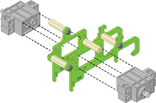
 Note: Both 180° Servo Motors are snapped on the opposite side sides of the B5 Green Parts. The 180° Servo Motor’s Wire has to be passed through the servo cut profile of the B5 Green Parts.
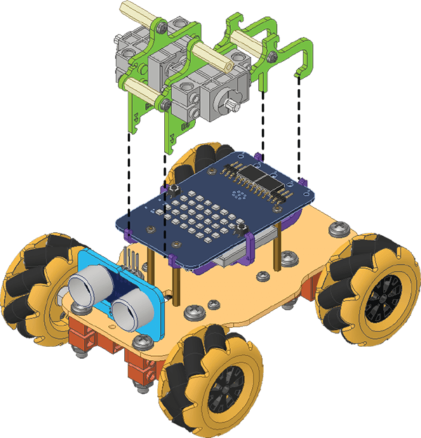
 - Snap the B5 Green Parts on the Quarky as shown below.
Assembled:
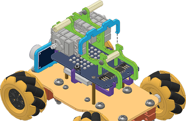
- Lock the B5 Green Parts by snapping the B6 Blue Part.
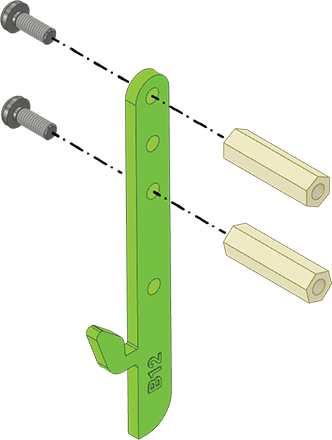
- For the next sub-assembly, attach the two M3 Spacers (20mm) to the B12 Green Part with M3 Bolts (8mm).
- Now attach two more M3 Spacers (20mm) on the opposite side of the same B12 Green Part with the M3 Bolts (8mm).
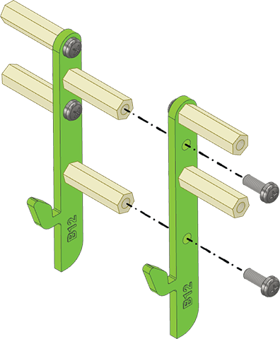
- Now attach two more M3 Spacers (20mm) to the other B12 Green Part with the M3 Bolts (8mm) on the opposite side.
- Align the two B12 Green Parts and fix them with the M3 Bolts (8mm). We will call this subassembly – Hook Assembly.
- Attach the B10 Green Part to the M3 Spacer (20mm) of the Hook Assembly with the M3 Bolt (8mm).
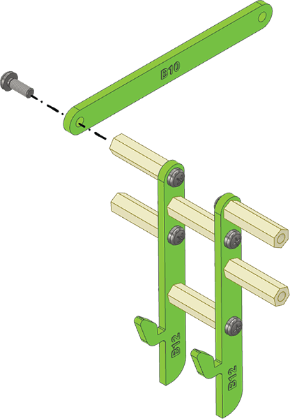 Note: Fix M3 Bolt (8mm) into the M3 Spacer (20mm) such that the parts can still rotate freely.
 - On the opposite side, attach another B10 Green Part to the M3 Spacer (20mm) of the Hook Assembly with the M3 Bolt (8mm).
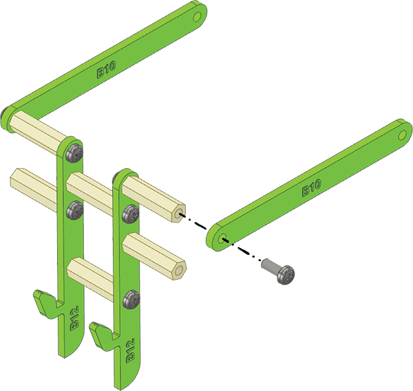 Note: Fix M3 Bolt (8mm) into the M3 Spacer (20mm) such that the parts can still rotate freely.
 - Now, attach the other ends of the B10 Green Parts to the M3 Spacers (20mm) of the B5 Green Part with the M3 Bolts (8mm).
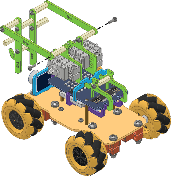 Note: Fix M3 Bolts (8mm) into the M3 Spacers (20mm) such that the parts can still rotate freely.
 - Now align and snap the B11 Green Part on the 180° Servo Motor’s shaft. Attach the other side of the B11 Green Part to the Hook Assembly with the M3 Bolt (8mm).
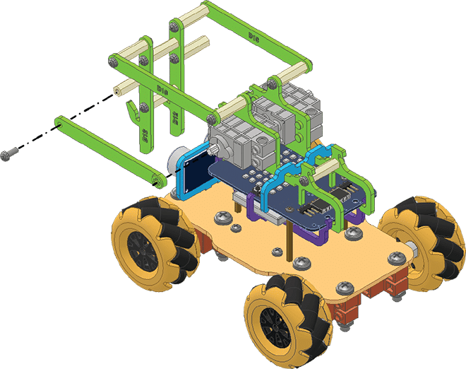 Note: The B11 Green Part must be parallel to Quarky at the time of assembly. Fix M3 Bolts (8mm) into the M3 Spacers (20mm) such that the parts can still rotate freely.
 - Align and snap the other B11 Green Part on the other 180° Servo Motor’s shaft. Attach the other side of the B11 Green Part to the Hook Assembly with the M3 Bolt (8mm).
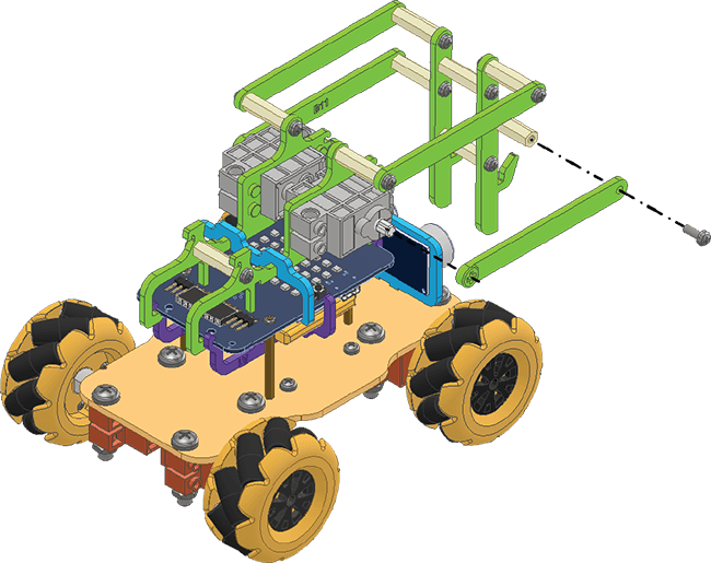 Note: Fix M3 Bolts (8mm) into the M3 Spacers (20mm) such that the parts can still rotate freely.
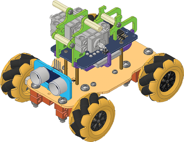
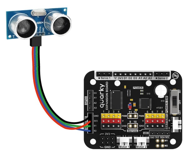
 - Attach the Ultrasonic Wire to the Ultrasonic Sensor and pass it from the wiring hole on the Body Plate.
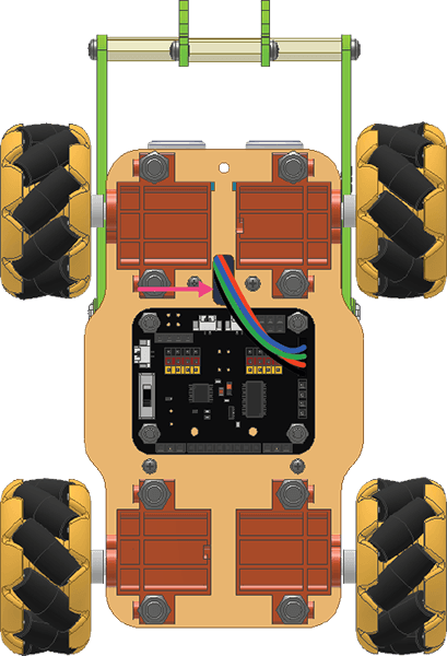
- Connect the Ultrasonic Wire to the Expansion Board according to the Wiring Diagram.
- Connect the Servo Motors to the Quarky Expansion Board.
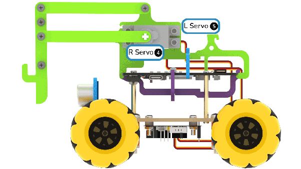
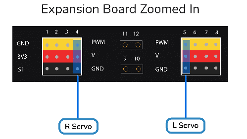
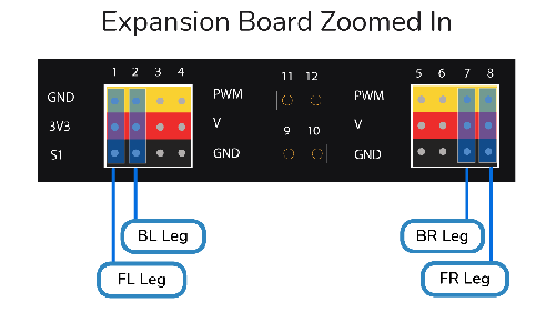
- Make sure the servo motors for the wheels are connected properly:
Your robot is ready:
Conclusion
In this lesson, we learned how to assemble the Pick and Place Quarky Mecanum Wheel Robot. We followed the steps and instructions to assemble the robot and connect the components. We connected the servo motors, ultrasonic sensor, and Quarky Expansion Board to the robot. Now you are ready to program your robot and explore its features.