Introduction
The Pin State Monitor module is one of the most useful modules to debug your sensors and calibrate them for your program. This module provides you with the real-time status of all the digital and analog pins.
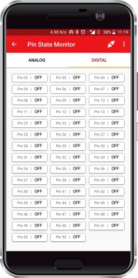
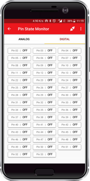
Digital Pins Monitor
This shows the values of all the digital pins states. The state is shown in the form of ON or OFF, where the ON state means the state of the pin is HIGH (5V) and the OFF state means the state of the pin is LOW (0V).
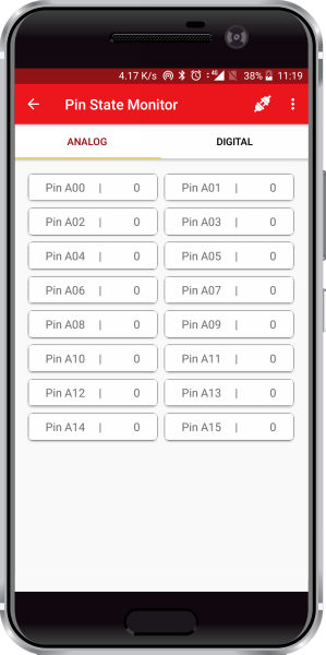
Analog Pins Monitor
This shows the analog value of the voltage on the analog input pins. The value is shown from 0 to 1023, which is mapped to the voltage from 0 to 5V.
For example, if the value shown on the monitor is 512, then the voltage value will be approximately 5*(512/1023) = 2.5V.
Arduino IDE Functions
Header
To include the Pin Monitor module in the Arduino program, you have to include the following header:
#define CUSTOM_SETTINGS
#define INCLUDE_PINMONITOR_MODULE
After defining the above mention headers, you have to include the dabble library:
#include <Dabble.h>
You can download the zip of Dabble-Arduino (for evive, Uno, Mega, and Nano) or Dabble-ESP32 depending board you are using.
Enabling Bluetooth Communication
For evive and Arduino Mega, Uno, and Nano
Dabble.begin(Baud_Rate);
Here Baud_Rate is the baud rate set for the Bluetooth module. With evive, you normally get 115200 baud rate modules.
For ESP32
Dabble.begin("Bluetooth_Name");
In place of Bluetooth_Name enter the name that you want to keep for Bluetooth of ESP32. The default name given in the library is “MyEsp32”.
Refreshing the data
To refresh the data that the device has got from the mobile app, you have to use the following line of code:
Dabble.processInput();
Functions
If you want to refresh the pin state in your app, you have to use the following functions to do it:
- PinState.sendDigitalData() : This function sends all the digital pin state to the app.
- PinState.sendAnalogData() : This functions sends all the analog pin state to the app.
You have to add a delay between sending data to the app. This delay should be greater than 20 microseconds to achieve smooth functionality of the module.
PictoBlox Blocks
There is a stacked block named as “ enable pin state monitor” and its function is to enable the Pin State Monitor feature of Dabble.


Examples
Arduino Code
In order to send the status of digital and analog pins of your board copy code as per your board from below mentioned board-wise codes or navigate to “Files>>Examples>>Dabble>>” and open “PinStateMonitor” for your board.
evive
/*
   Pin State Monitor is made for monitoring status of analog and digital pins of your board.
   In this example bluetooth is to be connected on HardwareSerial0 for Uno and Nano Boards.

   You can reduce the size of library compiled by enabling only those modules that you want
   to use. For this first define CUSTOM_SETTINGS followed by defining INCLUDE_modulename.

   Explore more on: https://thestempedia.com/docs/dabble/pin-state-monitor-module/
*/

#define CUSTOM_SETTINGS
#define INCLUDE_PINMONITOR_MODULE
#include <evive.h>
#include <Dabble.h>


void setup() {
  /*
     NOTE: PinMonitor only displays status of the pins of your board. It does not configure pinMode of the pins.
     So if there is any necessity to define pinMode then declare it setup as per requirement.
  */
  Serial.begin(250000);    // make sure your Serial Monitor is also set at this baud rate.
  Dabble.begin(115200);    //Enter baudrate of your bluetooth.Connect bluetooth on Bluetooth port present on evive.
}

void loop() {
  Dabble.processInput();             //this function is used to refresh data obtained from smartphone.Hence calling this function is mandatory in order to get data properly from your mobile.
  PinMonitor.sendDigitalData();
  PinMonitor.sendAnalogData();
  delayMicroseconds(20);
}
Mega
/*
   Pin State Monitor is made for monitoring status of analog and digital pins of your board.
   In this example bluetooth is to be connected on HardwareSerial0 for Uno and Nano Boards.

   You can reduce the size of library compiled by enabling only those modules that you want
   to use. For this first define CUSTOM_SETTINGS followed by defining INCLUDE_modulename.

   Explore more on: https://thestempedia.com/docs/dabble/pin-state-monitor-module/
*/

#define CUSTOM_SETTINGS
#define INCLUDE_PINMONITOR_MODULE
#include <evive.h>
#include <Dabble.h>


void setup() {
  /*
     NOTE: PinMonitor only displays status of the pins of your board. It does not configure pinMode of the pins.
     So if there is any necessity to define pinMode then declare it setup as per requirement.
  */
  Serial.begin(250000);    // make sure your Serial Monitor is also set at this baud rate.
  Dabble.begin(115200);    //Enter baudrate of your bluetooth.Connect bluetooth on Bluetooth port present on evive.
}

void loop() {
  Dabble.processInput();             //this function is used to refresh data obtained from smartphone.Hence calling this function is mandatory in order to get data properly from your mobile.
  PinMonitor.sendDigitalData();
  PinMonitor.sendAnalogData();
  delayMicroseconds(20);
}
Uno and Nano
/*
   Pin State Monitor is made for monitoring status of analog and digital pins of your board.
   In this example bluetooth is to be connected on HardwareSerial0 for Uno and Nano Boards.

   Pin Connection:
   Bluetooth        UNO/NANO
   TX               0 (RX)
   RX               1 (TX)


   WARNING:
   Since HardwareSerial0 is also used for code uploading process as well, unplug bluetooth from your board while uploading code.
   You can upload code first and then connect bluetooth to your board after code has been uploaded successfully.

   You can reduce the size of library compiled by enabling only those modules that you want
   use. For this first define CUSTOM_SETTINGS followed by defining INCLUDE_modulename.

   Explore more on: https://thestempedia.com/docs/dabble/pin-state-monitor-module/
*/


#define CUSTOM_SETTINGS
#define INCLUDE_PINMONITOR_MODULE
#include <Dabble.h>


void setup() {
  /*
     NOTE: PinMonitor only displays status of the pins of your board. It does not configure pinMode of the pins.
     So if there is any necessity to define pinMode then declare it setup as per requirement.
  */
  Serial.begin(9600);      //Connect bluetooth to HardwareSerial0 pins 0 and 1 of you UNO/NANO board.
  Dabble.begin(Serial);    //PLEASE REMOVE BLUETOOTH WHILE UPLOADING CODE ON YOUR BOARD.
}

void loop() {
  Dabble.processInput();             //this function is used to refresh data obtained from smartphone.Hence calling this function is mandatory in order to get data properly from your mobile.    //this function is used to refresh data obtained from smartphone.Hence calling this function is mandatory in order to get data properly from your mobile.
  PinMonitor.sendDigitalData();
  PinMonitor.sendAnalogData();
}
ESP32
/*
   Pin State Monitor is made for monitoring status of analog and digital pins of your board.
   In this example bluetooth is to be connected on HardwareSerial0 for Uno and Nano Boards.

   NOTE: State for only  following pins can be seen on Pin State Monitor:
   | Screen Name  | GPIO Pins                          |
   | Digital      | 2,4,5,12,13,14,15,16,17,18,19,21   |
   |              | 23,25,26,27                        |
   | Analog       | 32,33,34,35,36,39                  |

   You can reduce the size of library compiled by enabling only those modules that you want
   to use. For this first define CUSTOM_SETTINGS followed by defining INCLUDE_modulename.

   Explore more on: https://thestempedia.com/docs/dabble/pin-state-monitor-module/
*/

#define CUSTOM_SETTINGS
#define INCLUDE_PINMONITOR_MODULE
#include <DabbleESP32.h>


void setup() {
  /*
     NOTE: PinMonitor only displays status of the pins of your board. It does not configure pinMode of the pins.
     So if there is any necessity to define pinMode then declare it setup as per requirement.
  */
  Serial.begin(115200);    // make sure your Serial Monitor is also set at this baud rate.
  Dabble.begin("MyEsp32");    //set bluetooth name of your device
}

void loop() {
  Dabble.processInput();             //this function is used to refresh data obtained from smartphone.Hence calling this function is mandatory in order to get data properly from your mobile.
  PinMonitor.sendDigitalData();
  PinMonitor.sendAnalogData();
  delayMicroseconds(20);
}
PictoBlox
To enable the Pin State Monitor feature for the very first time, you have to upload the following script in upload mode:
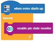
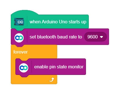
The above script only works with evive, for working with Mega, Uno or Nano replace the head block “when evive starts up” with a start-up block corresponding to your board and also start to add a set baud rate block. Pictoblox currently does not support ESP32; however, it will be added soon.
An example script for Uno is shown below: