Camera Module
The Camera module allows you to use your mobile camera for different activities like recording videos, capturing images, color detection, and face detection. Depending on the type of activities you want to do with your mobile camera the module is further divided into four modules each capable of executing a specific activity.
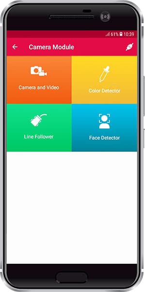
These modules are:
- Camera and Videos
- Color Detector
- Line Follower (Coming Soon)
- Face Detector (Coming Soon)
Color Detector module
This module processes live video streams and detect colors as per the selected settings.
![]()
There are various settings available.
Camera Preview
To visualize whether the Smartphone’s camera is positioned correctly, use this feature for toggling between the video stream and colors detected. You can toggle between them with the help of the preview icon present above the flash icon on your screen.
![]()
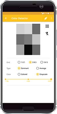
Grid Size
The video stream will be divided into the grid and each grid cell will result in one color. Available grid size:
- 1×1 (single cell)
- 3×3 (9 cells)
- 5×5 (25 cells).
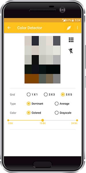
Number of color bits
To easily handle the total number of distinct colors resulting after processing, you can select the resolution by setting the bit size. For e.g., in grayscale mode, set a bit size of 1 to classify colors as white or black, and in colored mode, set a bit size of 3 to classify a color between 8 colors (because red, green, and blue can either be present or not, then there are 8 possible combinations). The bit size defines the number of color levels in which any image color will be classified.
The image below shows a 3×3 grid setting with 15-bit color settings.
Color Mode
Colored or Grayscale. In the colored mode, each cell will result in three values Red, Green, and Blue. In the grayscale mode, one value of gray level will be transmitted for Red, Green and Blue components. Value range (8-bit value for each color): max 255 and min 0.
The below image shows a 3×3 grid in grayscale color mode.
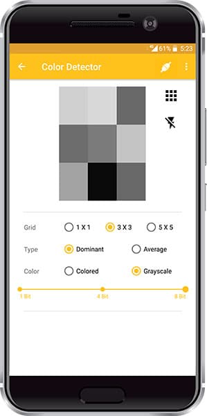
Color detection method
Dominant or Average. In the dominant method, color detection will find the most dominant color present in each cell. It helps in projects where there is a continuous change between colors. In the average method, it averages the color of each pixel in the cell.
Flash on/off
As per the availability of light, you can choose flash to be on or off. Note: avoid reflecting surfaces in flash-on mode.
You can control the settings of the grid, color mode, the number of bits for color detection and color calculation mode from the user interface present in the module and also from commands sent through hardware.
Arduino IDE Functions
Header
To include the Camera and Video module in the Arduino program, you have to include the following header:
#define CUSTOM_SETTINGS
#define INCLUDE_CAMERA_MODULE
After defining the above mention headers, you have to include the dabble library:
#include <Dabble.h>You can download the zip of Arduino Library depending on the board you are using:
- evive, Uno, Mega, and Nano – Dabble-Arduino
- ESP32 – Dabble-ESP32
Enabling Bluetooth Communication
To enable Bluetooth communication, you have to initialize serial communication using the following code:
- For evive and Arduino Mega, Uno, and Nano
Dabble.begin(Baud_Rate);Here Baud_Rate is the baud rate set for the Bluetooth module. With evive, you normally get 115200 baud rate modules.
- For ESP32
Dabble.begin("Bluetooth_Name");In place of Bluetooth_Name enter the name that you want to keep for Bluetooth of ESP32. The default name given in the library is “MyEsp32”.
Refreshing the data
To refresh the data that the device has got from the mobile app, you have to use the following line of code:
Dabble.processInput();Functions
Following are the function available for the Color Detector module:
- setColorScheme(schemeName) – In this function you pass the color scheme name as argument. Here there are certain constants(macros) defined that can be passed as an argument to set different color scheme. These constants are as follows:
- RGB_3bit – to set RGB color scheme with 3-bit resolution. 3-bit resolution means any color detected by the color detector module will be classified into 2^3 (eight color levels)
- RGB_15bit – to set RGB color scheme with 15-bit resolution. 15-bit resolution means any color detected by the color detector module will be classified into 2^15 color levels.
- RGB_24bit – to set RGB color scheme with 24-bit resolution. 24-bit resolution means any color detected by the color detector module will be classified into 2^24 color levels.
- GRAYSCALE_1bit – to set GRAYSCALE color scheme with 1-bit resolution. 1-bit resolution means an object will be classified as black or white.
- GRAYSCALE_4bit – to set GRAYSCALE color scheme with 4-bit resolution. 4-bit resolution means an object’s color will be classified into 2^4 grey levels ranging from black to white.
- GRAYSCALE_8bit – to set GRAYSCALE color scheme with 8-bit resolution. 8-bit resolution means an object’s color will be classified into 2^8 grey levels ranging from black to white.
- setGridSize(GridSize) – This function helps in setting the grid to a size that you want your camera screen to be divided. Replace GridSize with macros like GRID_1x1, GRID_3x3, and GRID_5x5 to get a grid of 1×1, 3×3, or 5×5 respectively.
- setCalculationMode(colorCalculationMode) – This function sets the color calculation mode. It will be Average or Dominant as stated above. Corresponding to these macros are DOMINANT and AVERAGE.
- sendSettings(&functionName) – This function is used to call a function that helps in the initialization of the camera settings for the color detector module. That function is passed by reference as an argument in the send settings function
- getRedColor() – returns red level value in RGB or GRAYSCALE mode for 1×1 grid
- getGreenColor() – returns green level value in RGB or GRAYSCALE mode for 1×1 grid
- getBlueColor() – returns blue level value in RGB or GRAYSCALE mode for 1×1 grid
- getRedColor(row,cols) – returns the red level value in RGB or GRAYSCALE mode for cell determined by parameter row and cols for the grid of size 3×3 and 5×5.
- getGreenColor(row,cols) – returns the green level value in RGB or GRAYSCALE mode for cell determined by parameter row and cols for the grid of size 3×3 and 5×5.
- getBlueColor(row,cols)– returns the blue level value in RGB or GRAYSCALE mode for cell determined by parameter row and cols for the grid of size 3×3 and 5×5.
- getGrayScaleColor(row,cols) – returns a gray level color value for the module when color mode is selected as grayscale. In colored mode, this function returns -1.
- checkColor(colorArray, colorName) – It returns 0 or 1 depending on the fact that if the color array passed is the same colorName passed-in function. This function runs on a small algorithm that is able to identify if the color is red, blue, green, yellow, or violet.
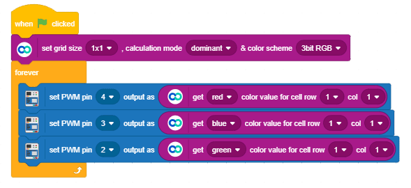
PictoBlox Blocks
There are 2 blocks in Dabble Extension of PictoBlox:
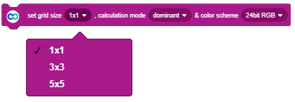
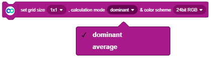
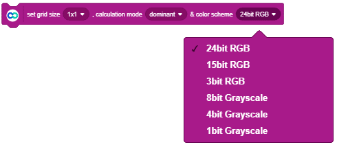
- “set grid size (), calculation mode () & color scheme ()” is a stacked block used for setting grid size, color calculation mode, and color mode settings. The block consists of three drop-downs.
- Drop down of grid size has three grid settings options mainly 1×1, 3×3, and 5×5 as stated above.
- Similarly, the drop-down of color calculation mode has options of Dominant and Average.
- And the drop-down color scheme has various color modes like 24-bit RGB, 15 -bit RGB, 3-bit RGB, 8-bit Grayscale, 4-bit Grayscale, and 1-bit Grayscale.
- Drop down of grid size has three grid settings options mainly 1×1, 3×3, and 5×5 as stated above.
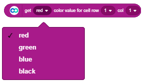
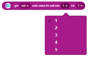
- “get () color value for cell row () col () ” is a reporter block it gives the value of the selected color component for the selected cell. There is one drop-down for selecting the color component and two drop-downs of rows and cells for selecting a cell. You can get the Red, Green, Blue, or Black (GrayScale) component for cells selected by the row and col drop downs having 1 to 5 values. You should select the cell value as per the currently active grid in the app. For example, if a 3×3 grid is active then there are three rows and three columns. Hence the maximum row and col value selected should be 3. If row and col value exceed 3, then the block returns -1 signifying an invalid cell address.


Examples
Arduino IDE
Follow the steps:
- Copy code as per your board in Arduino IDE and upload it.
- Connect with Dabble app via Bluetooth.
You can also find this code in Arduino IDE by navigating to “File>>Examples>>Dabble>>” and select the “PredictColor” example as per your board.
evive
/*
   Color detector module process live actions viewed by camera and gives color as per selected settings.

   You can reduce the size of library compiled by enabling only those modules that you want
   to use. For this first define CUSTOM_SETTINGS followed by defining INCLUDE_modulename.

   This code helps you in identifying basic colors namely red, blue, green, yellow and violet.
   The method present in the library allows you to differentiate only these 5 colors.
   Explore more on: https://thestempedia.com/docs/dabble/
*/
#define CUSTOM_SETTINGS
#define INCLUDE_COLORDETECTOR_MODULE
#include <evive.h>
#include <Dabble.h>

void initialSetup()
{
  ColorDetector.setGridSize(GRID_1x1);
  ColorDetector.setCalculationMode(DOMINANT);
  ColorDetector.setColorScheme(RGB_24BIT);
}
//to store red, green and blue color component values
int color[3] = {-1, -1, -1};  //store data in this array in R,G,B sequence. All three color components initialised to -1.
void setup() {
  Serial.begin(250000);  // make sure your Serial Monitor is also set at this baud rate.
  Dabble.begin(115200);  //Change this baudrate as per your bluetooth baudrate. Connect bluetooth on digital pin 2(RX) and 3(TX) for Uno/Nano and on Serial3 pins for Mega.
  ColorDetector.sendSettings(&initialSetup);
}

void loop() {
  Dabble.processInput();  //this function is used to refresh data obtained from smartphone.Hence calling this function is mandatory in order to get data properly from your mobile.
  //Store color components
  color[0] = ColorDetector.getRedColor();
  color[1] = ColorDetector.getGreenColor();
  color[2] = ColorDetector.getBlueColor();
  Serial.print("Color Found: ");
  if(ColorDetector.checkColor(color,RED) == 1)
  {
    Serial.println("Red");
  }
  else if(ColorDetector.checkColor(color,GREEN) == 1)
  {
    Serial.println("Green");
  }
  else if(ColorDetector.checkColor(color,BLUE) == 1)
  {
    Serial.println("Blue");
  }
  else if(ColorDetector.checkColor(color,YELLOW) == 1)
  {
    Serial.println("Yellow");
  }else if(ColorDetector.checkColor(color,VIOLET) == 1)
  {
    Serial.println("Violet");
  }
  else{
    Serial.println("None");
  }
}
Mega, Uno, and Nano
/*
   Color detector module process live actions viewed by camera and gives color as per selected settings.

   NOTE:
   1)For Arduino Mega Connect Bluetooth on Serial3 pins.
   2)For Arduino Uno/Nano library uses SoftwareSerial,hence pin 2 and pin 3 are used
   as RX and TX pins respectively on SoftwareSerial.Hence with arduino Uno
   follow below connections for bluetooth.
   UNO  - BLUETOOTH
   2    - TX
   3    - RX
   3)For Uno/Nano keep bluetooth Baudrate below 38400.

   You can reduce the size of library compiled by enabling only those modules that you want
   to use. For this first define CUSTOM_SETTINGS followed by defining INCLUDE_modulename.

   This code helps you in identifying basic colors namely red, blue, green, yellow and violet.
   The method present in the library allows you to differentiate only these 5 colors.
   Explore more on: https://thestempedia.com/docs/dabble/
*/
#define CUSTOM_SETTINGS
#define INCLUDE_COLORDETECTOR_MODULE
#include <Dabble.h>

void initialSetup()
{
  ColorDetector.setGridSize(GRID_1x1);
  ColorDetector.setCalculationMode(DOMINANT);
  ColorDetector.setColorScheme(RGB_24BIT);
}
//to store red, green and blue color component values
int color[3] = {-1, -1, -1};  //store data in this array in R,G,B sequence. All three color components initialised to -1.
void setup() {
  Serial.begin(9600);  // make sure your Serial Monitor is also set at this baud rate.
  Dabble.begin(9600);  //Change this baudrate as per your bluetooth baudrate. Connect bluetooth on digital pin 2(RX) and 3(TX) for Uno/Nano and on Serial3 pins for Mega.
  ColorDetector.sendSettings(&initialSetup);
}

void loop() {
  Dabble.processInput();  //this function is used to refresh data obtained from smartphone.Hence calling this function is mandatory in order to get data properly from your mobile.
  //Store color components
  color[0] = ColorDetector.getRedColor();
  color[1] = ColorDetector.getGreenColor();
  color[2] = ColorDetector.getBlueColor();
  Serial.print("Color Found: ");
  if(ColorDetector.checkColor(color,RED) == 1)
  {
    Serial.println("Red");
  }
  else if(ColorDetector.checkColor(color,GREEN) == 1)
  {
    Serial.println("Green");
  }
  else if(ColorDetector.checkColor(color,BLUE) == 1)
  {
    Serial.println("Blue");
  }
  else if(ColorDetector.checkColor(color,YELLOW) == 1)
  {
    Serial.println("Yellow");
  }else if(ColorDetector.checkColor(color,VIOLET) == 1)
  {
    Serial.println("Violet");
  }
  else{
    Serial.println("None");
  }
}
PictoBlox
In the script given below, the color of an RGB led is changed as per the color detected by the Color Detector module.