Introduction
The LED Brightness Control is the first module of the Dabble App.
This module allows you to control the output of the digital pins in two ways:
- If the pin is a digital pin with no PWM support, then you can control the HIGH and LOW state of the pin by clicking on the ON/OFF icon present in the center of the module.
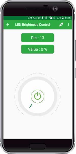
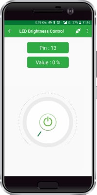
LED Brightness module controlling digital pin 13. The current state of LED is set to OFF.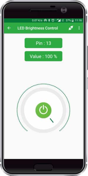
LED Brightness module controlling Digital Pin13. The current state of LED is set to ON. - If the digital pin is a PWM pin then you can also vary PWM of that pin in order to get different output voltage at that pin. Potentiometer type knob as seen in the image is used for controlling PWM. Knob range is from 0 to 100 and it is mapped to PWM values. The module is made for activities like controlling LEDs.
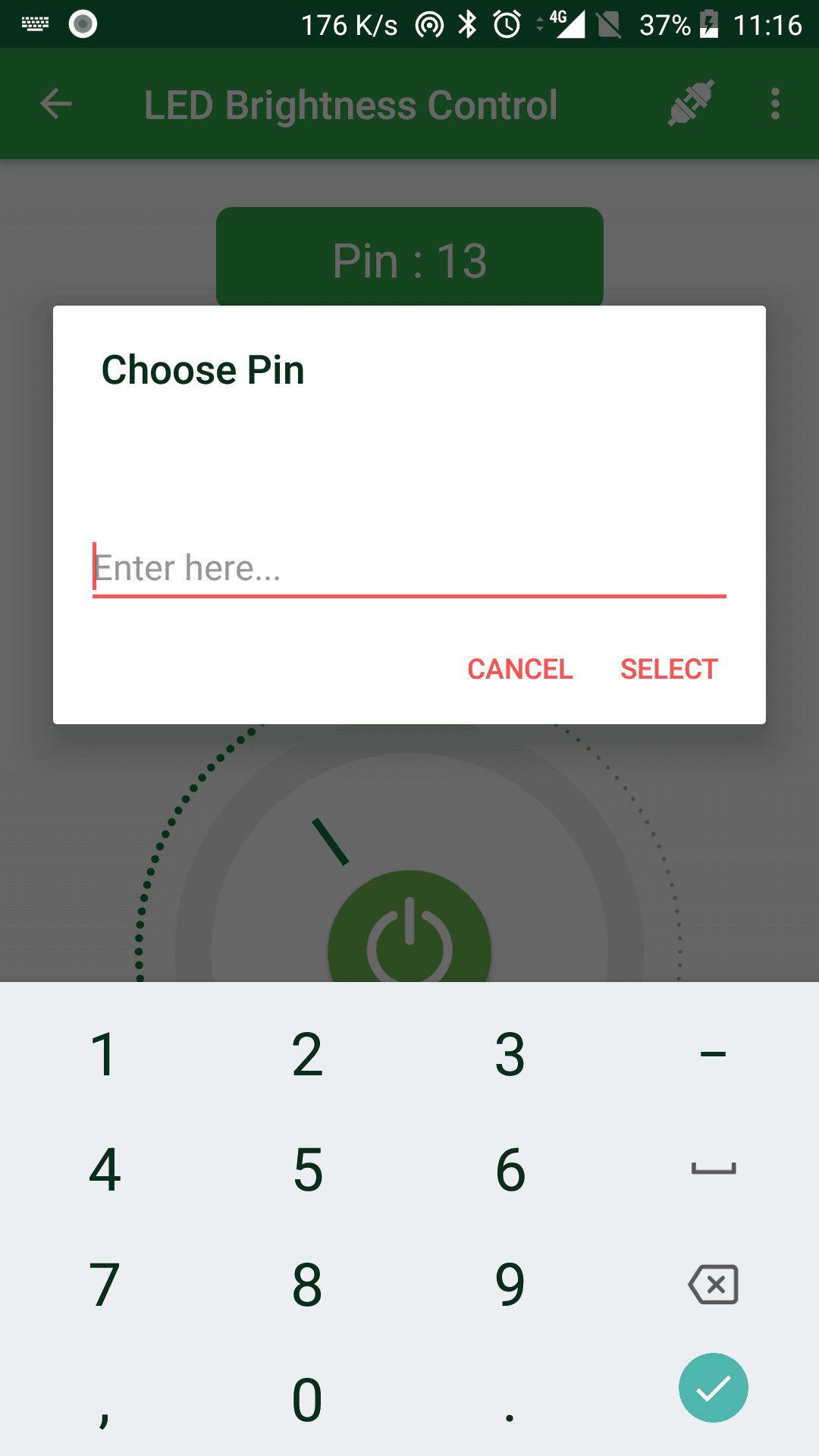
How to change the Pin?
To change the pin, you can click on the button showing the Pin (In the above image it is Pin: 13 button).
You can choose the following pins for the corresponding boards:
- evive:
- PWM pins: digital pins 2-13
- Digital pins with no brightness control: digital pins 21-26
- Arduino Uno:
- PWM pins: digital pins 3,5,6,9,10 and 11
- Digital pins with no brightness control: digital pins 2,4,7,8,12 and 13
- Arduino Mega:
- PWM pins: digital pins 2-13 and 44-46
- Digital pins with no brightness control: digital pins 14-43 and 47-53
Arduino IDE Functions
Header
To include the LED Control module in the Arduino program, you have to include the following header:
#define CUSTOM_SETTINGS
#define INCLUDE_LEDCONTROL_MODULE
After defining the above mention headers, you have to include the dabble library:
#include <Dabble.h>
You can download the zip of Arduino Library for depending on the board you are using.
- evive, Uno, Mega, and Nano – Dabble-Arduino
- ESP32 – Dabble-ESP32
Enabling Bluetooth Communication
To enable Bluetooth communication, you have to initialize serial communication using the following code:
- For evive and Arduino Mega, Uno, and Nano:
Dabble.begin(Baud_Rate);Here Baud_Rate is the baud rate set for the Bluetooth module. With evive, you normally get 115200 baud rate modules. - For ESP32
Dabble.begin("Bluetooth_Name");In place of Bluetooth_Name enter the name that you want to keep for Bluetooth of ESP32. The default name given in the library is “MyEsp32”.
Refreshing the data
To refresh the data that the device has got from the mobile app, you have to use the following line of code:
Dabble.processInput();
This function also changes the state and the brightness of the LED automatically and you don’t have to do anything.
Functions
If you want to get the pin number, its state, and brightness value of the LED from the module, then these are the functions using which you can do that:
- LedControl.getpinNumber(): This function returns the pin selected for LED Brightness control in the mobile app. The function returns int data type.
- LedControl.getpinState(): The function returns the state of the pin set by the user in the mobile app. This function returns the following output:
- 1 if the state is set to ON
- 0 if the state is set to OFF
- LedControl.readBrightness(): This function returns the brightness value set by the user in the mobile app. It returns int data type with a value ranging between 0 and 100.
PictoBlox (Scratch) Blocks
There is a stacked block named “enable LED control” available for this module. Its function is to enable the LED Brightness Control feature of Dabble.


Examples
Arduino IDE Example for LED Brightness Control Module
Here in this example, we are controlling the LED brightness and also displaying the pin number, state, and brightness of the LED on the serial monitor. Either copy the codes given below as per your selected board or you can also navigate to “Files>>Examples>>Dabble>>” and select the Led Brightness Control example as per your board.
evive
#define CUSTOM_SETTINGS
#define INCLUDE_LEDCONTROL_MODULE
#include <evive.h>
#include <Dabble.h>

void setup() {
Serial.begin(250000);
Dabble.begin(115200);     //Enter baudrate of your bluetooth.Connect bluetooth on Bluetooth port present on evive.

}

void loop() {
Dabble.processInput();
Serial.print("Led:");
Serial.print(LedControl.getpinNumber());
Serial.print('\t');
Serial.print("State:");          //0 if led is Off. 1 if led is On.
Serial.print(LedControl.getpinState());
Serial.print('\t');
Serial.print("Brightness:");
Serial.println(LedControl.readBrightness());
}
You can enter the pin value as 13 in the Dabble app since there is an in-built led present on evive at pin 13.
Arduino Mega, Uno and Nano
/*
   Led Brightness Control Module allows user to control any digital pin on their board. They can turn pin ON or OFF, can
   also vary its PWM if that functionality is supported on that pin.

   NOTE:
   1)For Arduino Mega Connect Bluetooth on Serial3 pins.
   2)For Arduino Uno/Nano library uses SoftwareSerial,hence pin 2 and pin 3 are used
   as RX and TX pins respectively on SoftwareSerial.Hence with arduino Uno
   follow below connections for bluetooth.
   UNO  - BLUETOOTH
   2    - TX
   3    - RX

   3)For Uno/Nano keep bluetooth Baudrate below 38400.

   You can reduce the size of library compiled by enabling only those modules that you want
   to   use. For this first define CUSTOM_SETTINGS followed by defining INCLUDE_modulename.

   Explore more on: https://thestempedia.com/docs/dabble/led-brightness-control-module/
*/

#define CUSTOM_SETTINGS
#define INCLUDE_LEDCONTROL_MODULE
#include <Dabble.h>

void setup() {
  Serial.begin(9600);    // make sure your Serial Monitor is also set at this baud rate.
  Dabble.begin(9600);    //Change this baudrate as per your bluetooth baudrate. Connect bluetooth on digital pin 2(RX) and 3(TX) for Uno/Nano and on Serial3 pins for Mega.

}

void loop() {
  Dabble.processInput();          //this function is used to refresh data obtained from smartphone.Hence calling this function is mandatory in order to get data properly from your mobile.
  Serial.print("Led:");
  Serial.print(LedControl.getpinNumber());
  Serial.print('\t');
  Serial.print("State:");          //0 means OFF, 1 means ON
  Serial.print(LedControl.getpinState());
  Serial.print('\t');
  Serial.print("Brightness:");
  Serial.println(LedControl.readBrightness());
}
To work with onboard led enter pin 13 in the Dabble app.
ESP32
/*
   This is Led brightness control example for ESP32 that uses LED Brightness Control Module in Dabble app.
   This module allows you to control state of pin. You can make pin HIGH or LOW or can also assign any PWM
   value to it.

   NOTE: As in esp32 any channel can be configured as a PWM channel hence any first eight pins controlled by Module
   will be treated as PWM and others will be treated as normal digital pins.


   You can reduce the size of library compiled by enabling only those modules that you want to
   use.For this first define CUSTOM_SETTINGS followed by defining INCLUDE_modulename.

   Explore more on: https://thestempedia.com/docs/dabble/getting-started-with-dabble/
*/
#define CUSTOM_SETTINGS
#define INCLUDE_LEDCONTROL_MODULE
#include <DabbleESP32.h>
unsigned long lasttime=0;
void setup() {
  Serial.begin(115200);     // make sure your Serial Monitor is also set at this baud rate.
  Dabble.begin("MyEsp32");     //set bluetooth name of your device
}

void loop() {
  Dabble.processInput();    //this function is used to refresh data obtained from smartphone.Hence calling this function is mandatory in order to get data properly from your mobile.
  //uncomment if you want to check if paramters read correctly
  /*Serial.print("Led:");
  Serial.print(LedControl.getpinNumber());
  Serial.print('\t');
  Serial.print("State:");          //0 if led is Off. 1 if led is On.
  Serial.print(LedControl.getpinState());
  Serial.print('\t');
  Serial.print("Brightness:");
  Serial.println(LedControl.readBrightness());*/
}
In some ESP32 dev modules onboard led comes on gpio pin 2, if your module has onboard led then you can use its corresponding pin to check the functionality of this module or else connect led to any pin and control it through the app.
PictoBlox Example for LED Brightness Control Module
To access the LED Brightness Control feature for the very first time, you have to upload the following script.
- Stage Mode
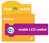 Note: When working with evive or any of your Arduino board on PictoBlox for the very first time, or if you’ve previously uploaded another code to your board, you must upload the firmware in order to work in stage mode.
 - Upload Mode
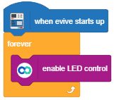
Depending upon your board type choose the corresponding head block. As seen in the example above with evive “when evive starts up” head block is chosen. Similarly, for the Arduino UNO board, you can choose the “when Uno starts up” block. Currently, PictoBlox supports evive and Arduino Uno, Nano, and Mega boards. Support for the ESP32 board will be added soon.