Introduction
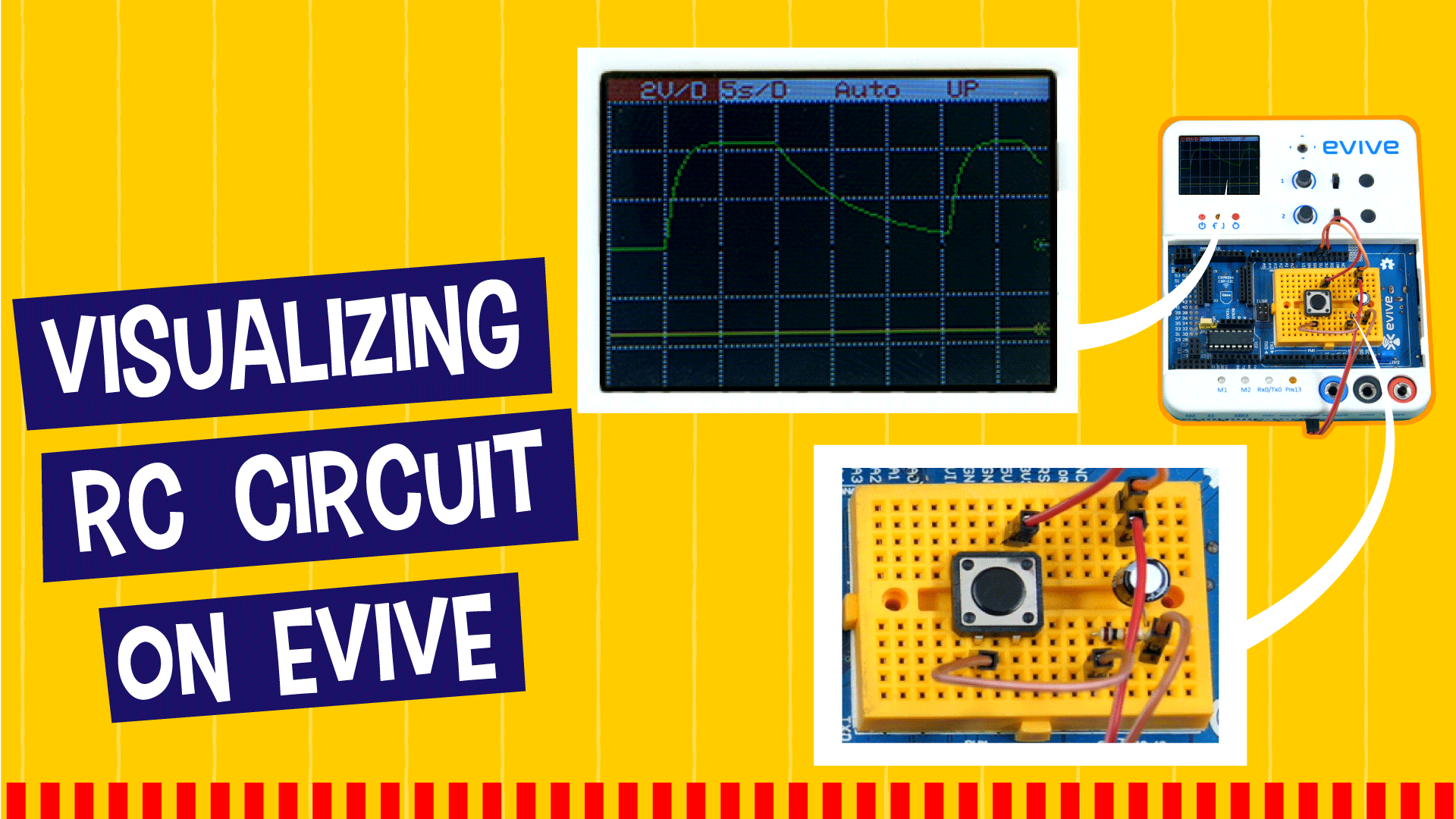
This project is for the Physics enthusiast in you! Learn the basics of a capacitor and an RC circuit, visualize the charging and discharging of an RC circuit, and its response to AC supply using evive’s oscilloscope and beta function generator.
Get ready to be RC-ed!
What is Capacitor?
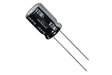
A capacitor is a device capable of storing electrical charges.
The maximum amount of charge that can be accumulated, divided by per unit potential difference is a property called capacitor capacitance (C) and is an indicator of the amount of energy it can store.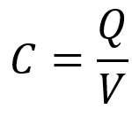
What is an RC Circuit?
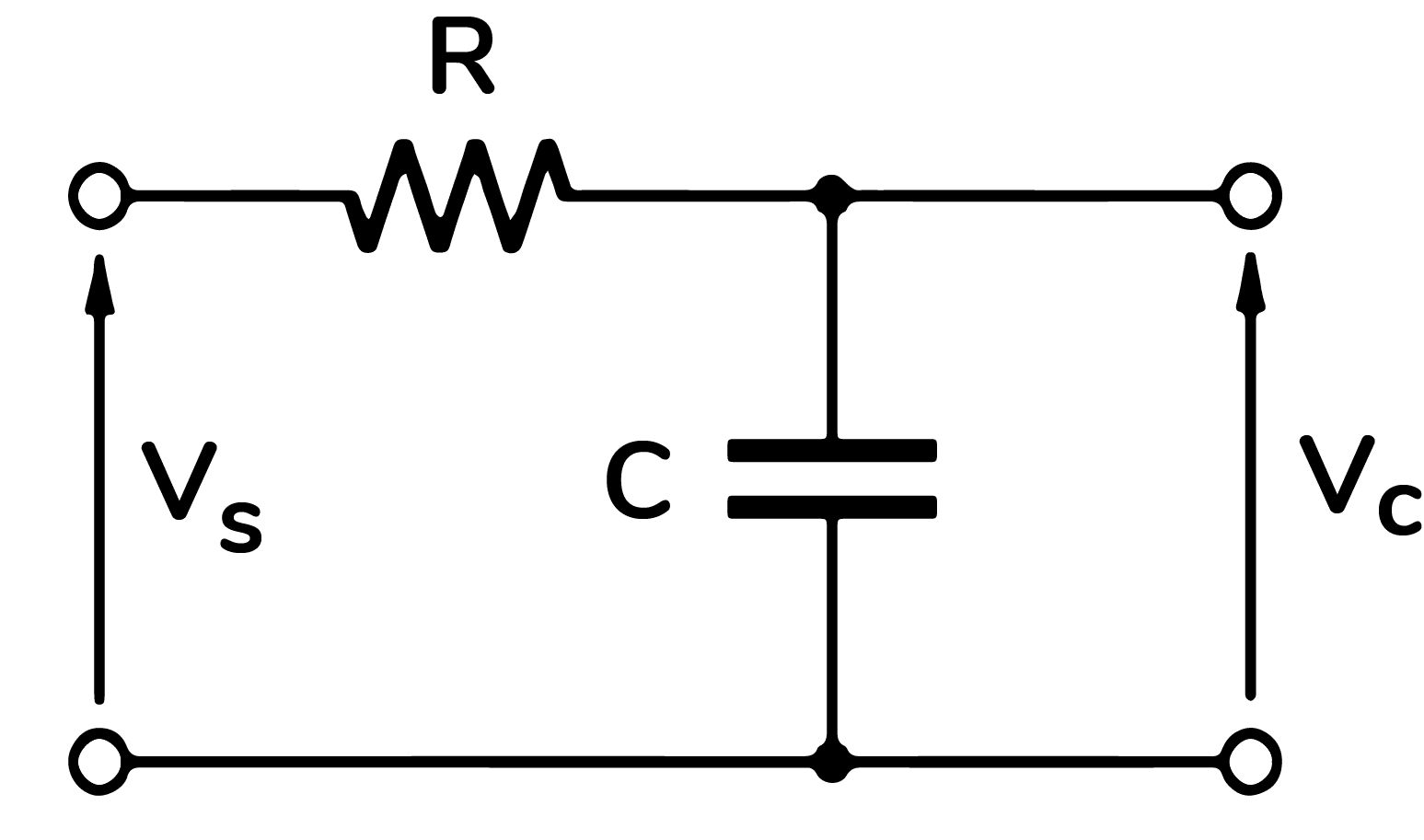
RC Circuit is the electric circuit which consists of Resistors and Capacitors. Here, Vs is the input voltage and Vc is the voltage across the capacitor. We will study the behavior of the Vc as the Vs changes.
RC Charging Circuit
The process of storing energy (when connected to a positive DC source) through the resistor until the voltage level across it reaches up to the input voltage level is called as charging of a capacitor. The circuit diagram can be drawn as: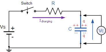
Source: electronics-tutorials
Capacitors are charged according to time by the equation:
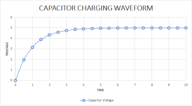
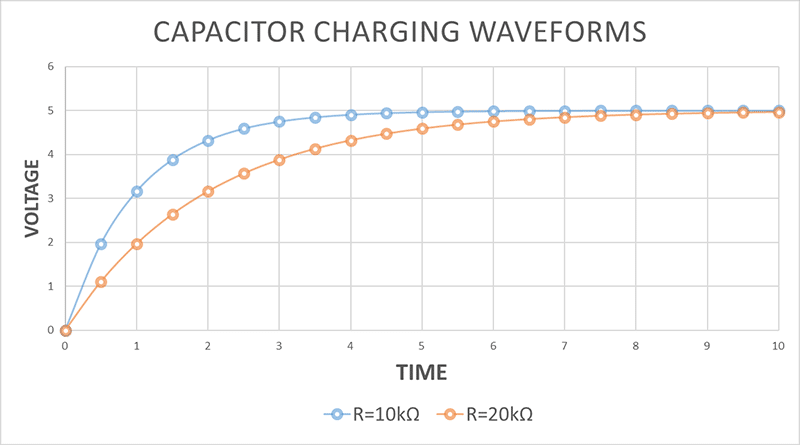
When we charge a capacitor, the voltage (or charge) increases with time. The graph of voltage (or charge) versus time is not linear but exponential (as shown in the figure below). After a time T =RC, the capacitor is 63% charged (or 0.63 x voltage of the battery V). T is a constant for a given capacitor and a given resistor. T is called the time constant.![]()
RC Discharging Circuit
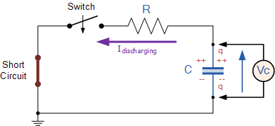
When the capacitor is fully charged and the power source is disconnected, the capacitor starts returning energy to the circuit through the resistor is called as discharging of a capacitor.
Source electronics-tutorial
Capacitors are discharged according to time by the equation:
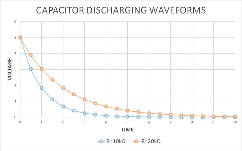
When we discharge a capacitor, the voltage (or charge) decreases with time. The graph of voltage (or charge) versus time is not linear but exponential (as shown in the figure below).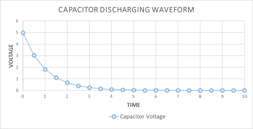
Effect of Resistors and Capacitors
On changing the values of Resistance and Capacitance, the graphs of the Charging Circuit and the Discharging Circuit also changes accordingly.
For the higher value of RC, the longer time will be taken for the capacitor to charge.
This behavior can be seen in the figure below:
RC Charging for different resistor values
RC Discharging for different resistor values
Visualizing RC Circuits
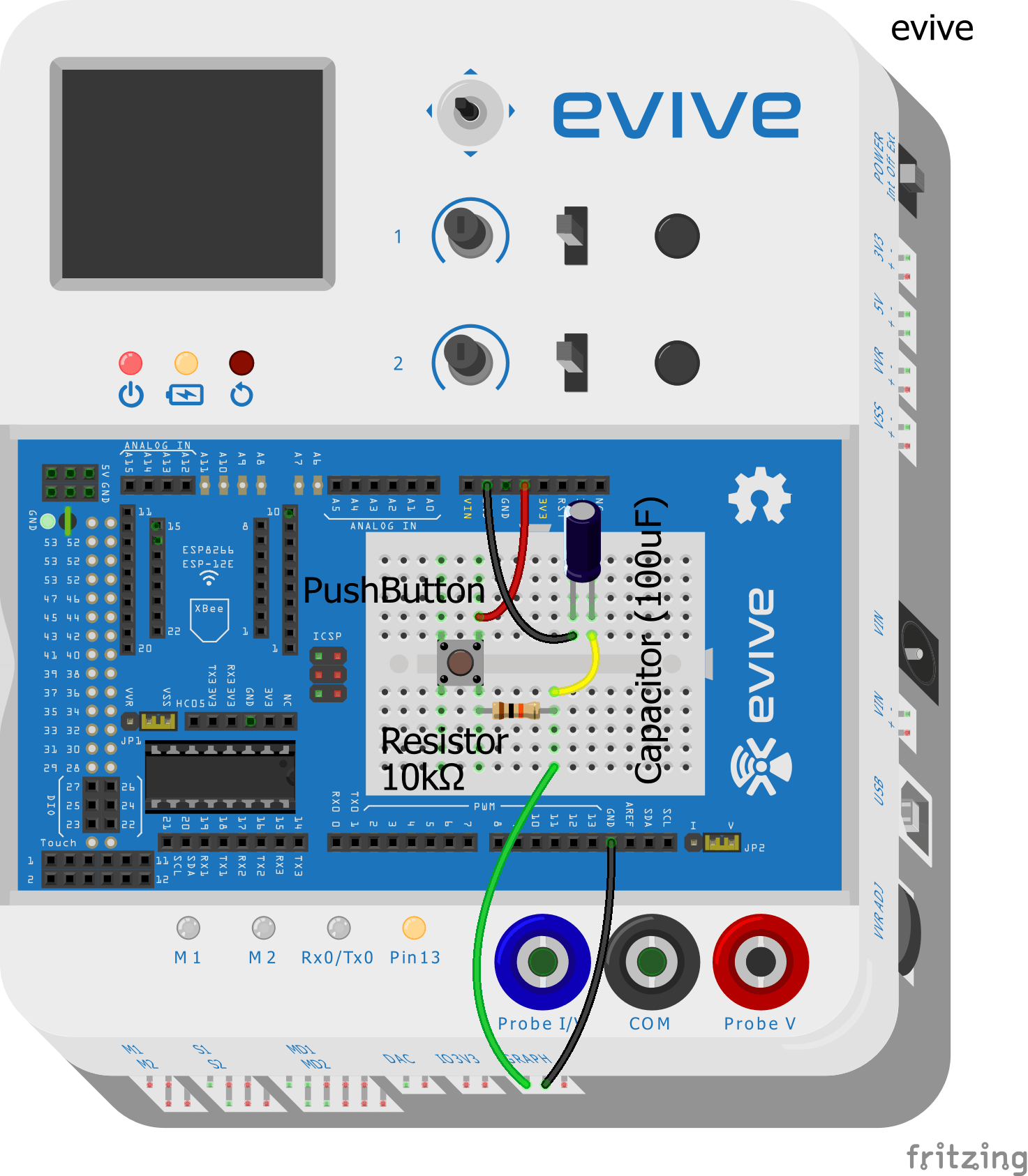
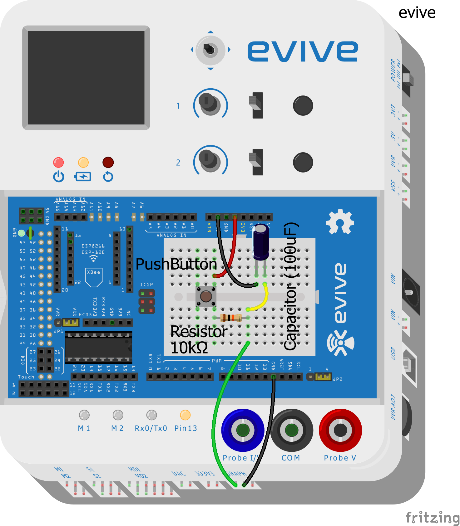
Make the following circuit using the resistor of value 10 kOhm and the capacitor of value 100 μF.
Once you make the connections, ON the evive.
DC Graphs
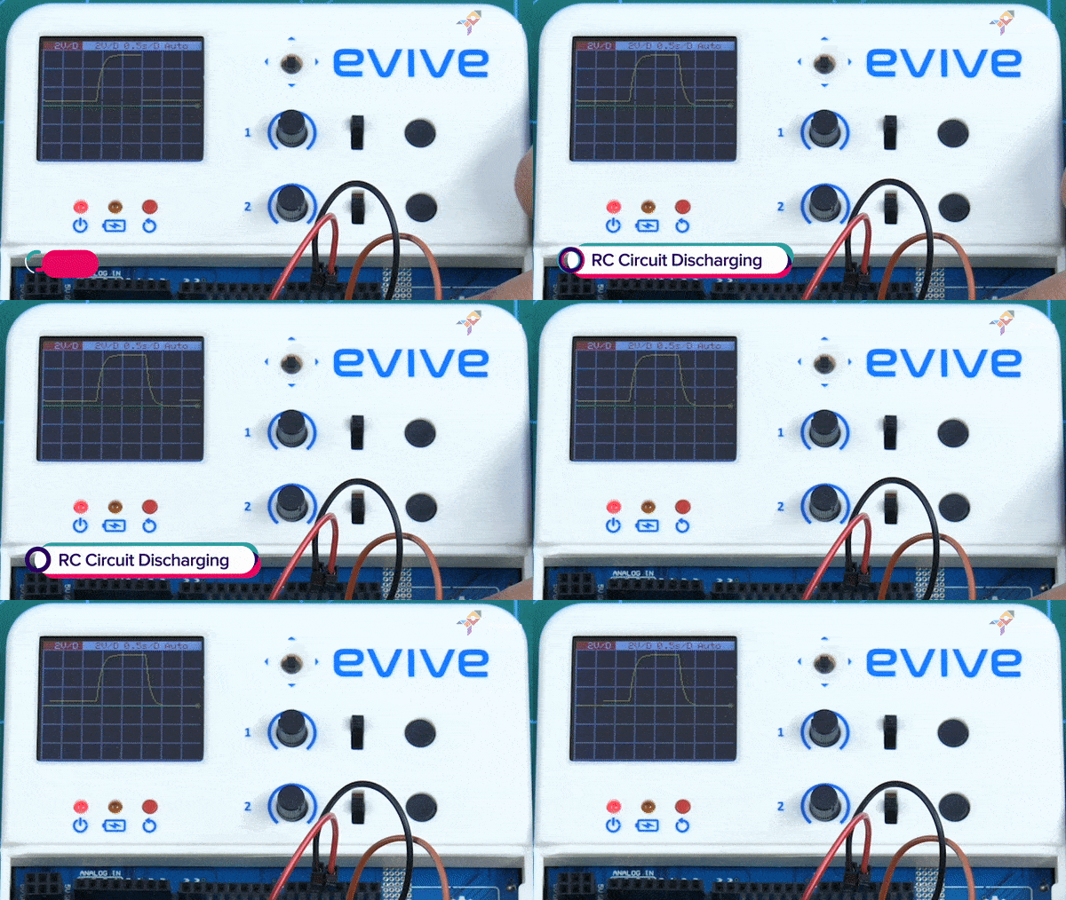
As you ON the evive, the evive Firmware shows. Open the option of Oscilloscope and see the waveforms.
RC Charging
RC Discharging
Conclusion
With this, you know what an RC circuit is and what goes on inside it when it connected to DC and AC inputs.
Three weeks into the campaign and the love keeps coming incessantly! In case you’re confused about what type of ‘love’ we’re talking about, go had a look at our Indiegogo campaign!

