
Introduction
If you love animated movies, then you most probably know how cute WALL-E is! And perhaps you wanted to have one at some point in time (don’t lie!). Well, now is the time, though with a few modifications of our own. Instead of the conventional robot that WALL-E is, we’re going to make one with *wait for it* feet!
So, grab all the stuff needed, pack in some DIYing, and let’s begin!
Psst! Just so you know, we’re launching something really exciting very soon! To know what it is, visit here!
Making
Let’s start by assembling our biped.
We have designed and 3d printed some parts of our biped. You can download those files from the code section below.
Take the foot of the biped and in the space given in it, insert the metal servo and fix it using the hot glue.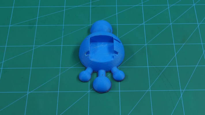
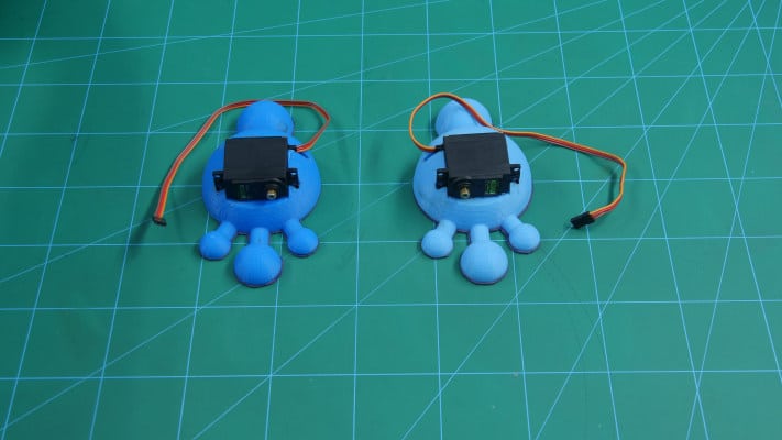
Now in the accessories of the metal servo, you will find one four-sided servo horn, take the horn and cut one of the sides and make it three sides.
Now fix this servo horn into the free servo head. Take the 3d printed leg of the biped and fix the servo horn to this with the help of screws.
Repeat the same process for the second leg.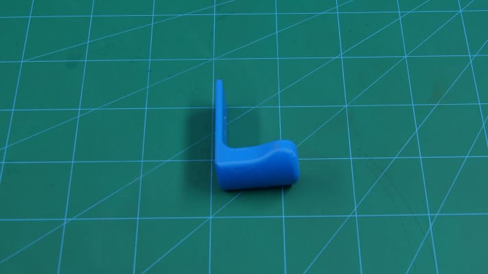

Once done with both the legs, take another metal servo and a double sided servo horn. Fix the servo horn onto the servo horn.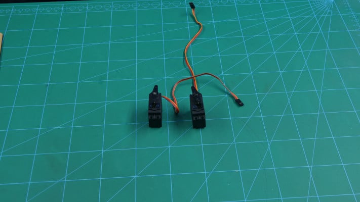
Now take the leg assembly and fix the servo horn on top of the leg using screws. Repeat the same process for the other leg.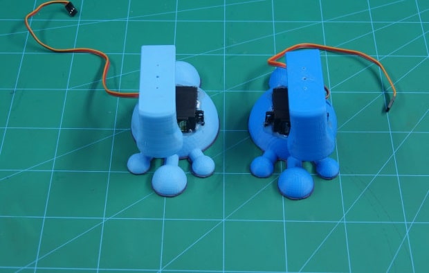
Take a base plate.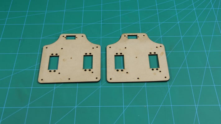
Fix both the free servos onto this plate using screws.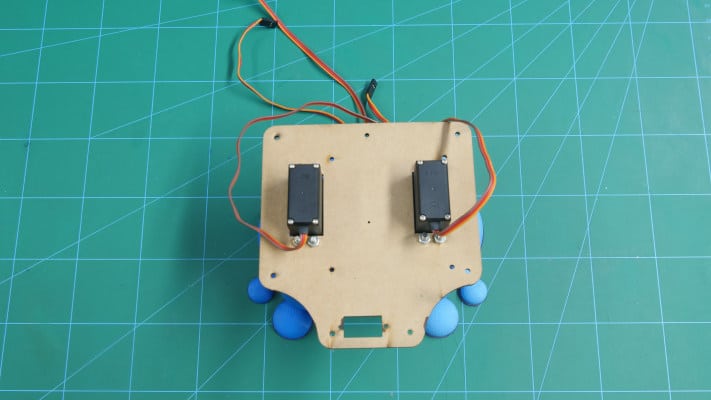
We need a platform to place our brain and the sensor. We’ll need another plate on top of this plate. To fix the plate we will mount 15mm standoffs on all the corners using screws.
Our biped will also be also an autonomous robot, which will avoid all the obstacles coming in its way. This to give our robot this ability, we are going to add the ultrasonic sensor.
Also, we need it to detect in the directions thus will be using a micro servo.
Take the other base plate and fix a micro servo at the front using screws.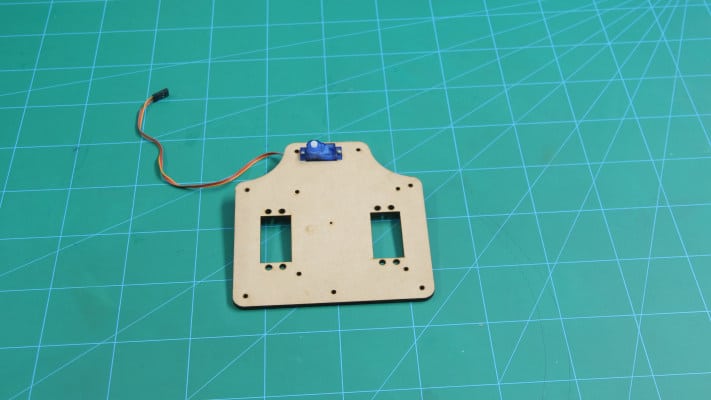
Take an ultrasonic sensor holder. Take the ultrasonic sensor and insert it into the holder.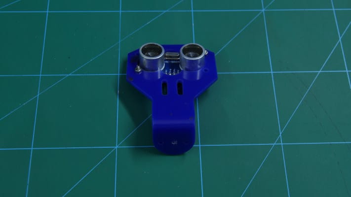
Now, take evive and fix it on top of the base plate and fasten it using chassis.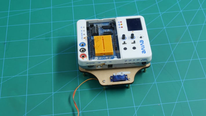
Take this plate and fix it on top of the other chassis using screws.
Now we have a 3d printed eyes for our biped, fix this eyes onto the ultrasonic sensor. Glue the ultrasonic holder on to the servo horn.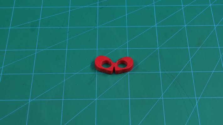
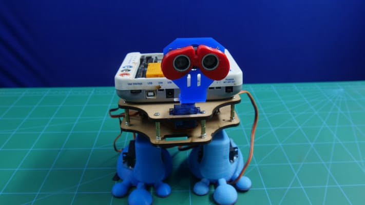
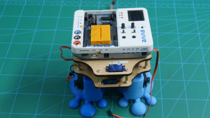
Our assembly is thus complete.
Connections
ake the connections as shown in the figure: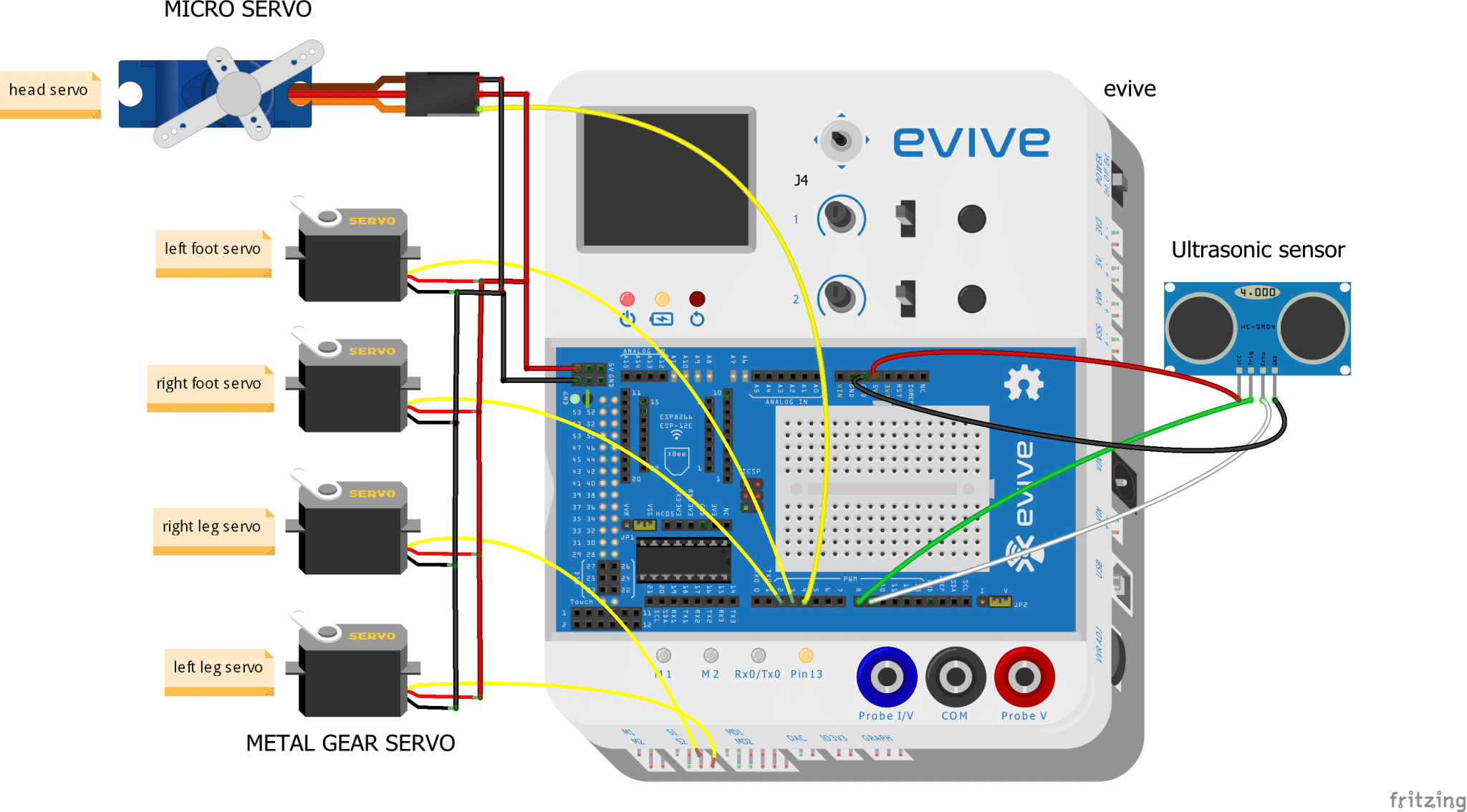
The GND and VCC of all the components should be connected to the GND and +5V of evive.
Signal Pins of servo:
- Head servo – Digital Pin 04
- Right foot servo – Digital Pin 02
- Left foot servo – Digital Pin 03
- Right Leg servo – S1
- Left Leg servo – S2
Ultrasonic Pins:
- Trigger – Digital Pin 08
- Echo – Digital Pin 09
Code
Upload the following code to evive:
Logic
The bottom two servos attached to the feet are used for the movement of the feet.
The servo on the top of the leg is used for the movement of the entire leg.
We have made the biped which is autonomous. Thus the ultrasonic sensor at the top is used to avoid the obstacles that come in the way.
The servo under the sensor is used for the movement of the sensor from 0 to 180.
The ultrasonic sensor senses the surrounding if there is no obstacle in its path it continues to move forward.
If the obstacle is detected it will turn left, if not it will continue in that direction. If the object is detected on left, it will turn right.
If the object is in all the three directions, it will move in reverse direction.
Conclusion
With this, your autonomous Biped robot is ready! Have fun watching it move around.


