
Introduction
In this project, we will make the robotic arm without any end effectors. There will be only two servo motors in the robot. One on the base and another on Link 1. We will control this robot using two potentiometers.
Assembly
- Mount servo horn on top inner bearing disc using self-threading M2 (“M2” represents a diameter of 2mm) screws of 8mm length. These screws can be found in servo accessories. Be careful about holes you are mounting the horn on (use holes closer to disk centre).


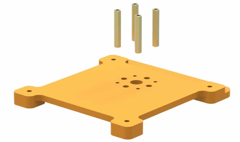
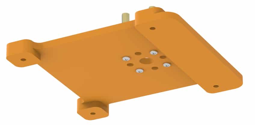
- Place 30 mm stand-offs on the base. Fasten using M3 bolts of 8mm length.

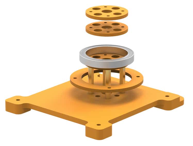
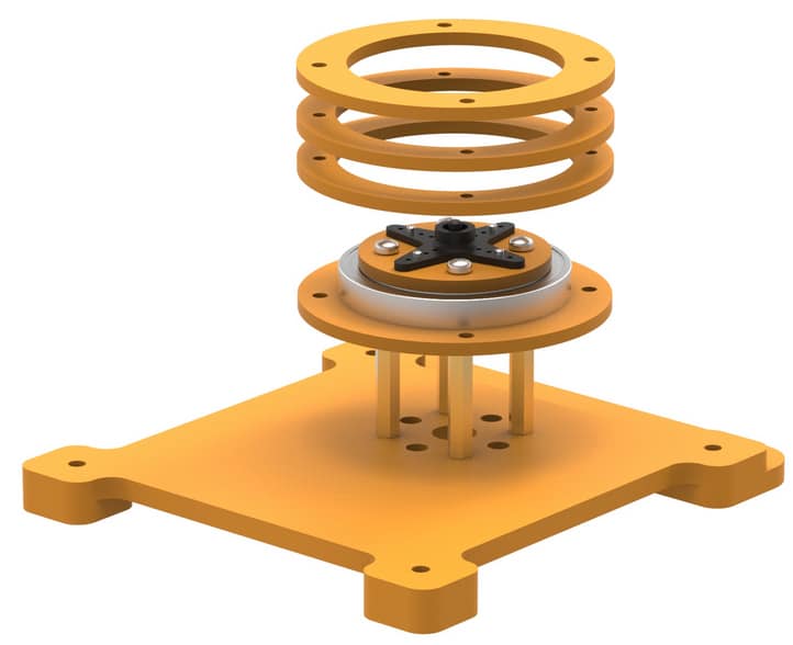
- Take the bottom outer bearing disc and slide it over standoffs.

- Mount bottom inner bearing disc on stand-offs. Align the disc such that smaller holes are in line with the stand-offs.

- Put the bearing on top of bottom inner bearing disc. Observe how disc supports the bearing from beneath.

- Next, place the two middle inner bearing discs. These will perfectly fit inside the bearing.
- Seat the “servo horn & top inner bearing disc” assembly on top of bearing as shown. Make sure all smaller holes in these discs are aligned since we will fasten them all together using 20mm M3 bolts.


- Place the middle outer bearing discs first and then top outer bearing disc as shown. The middle discs will have a larger inner diameter compared to the top and bottom ones. The inner diameters of the middle discs will be equal to the bearing’s outermost diameter.
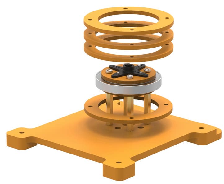
- Slide up the bottom outer bearing disc, align the holes in the discs and stack them.
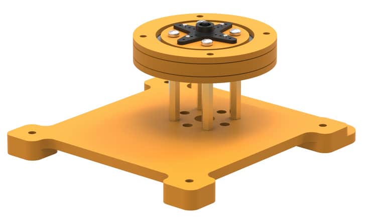
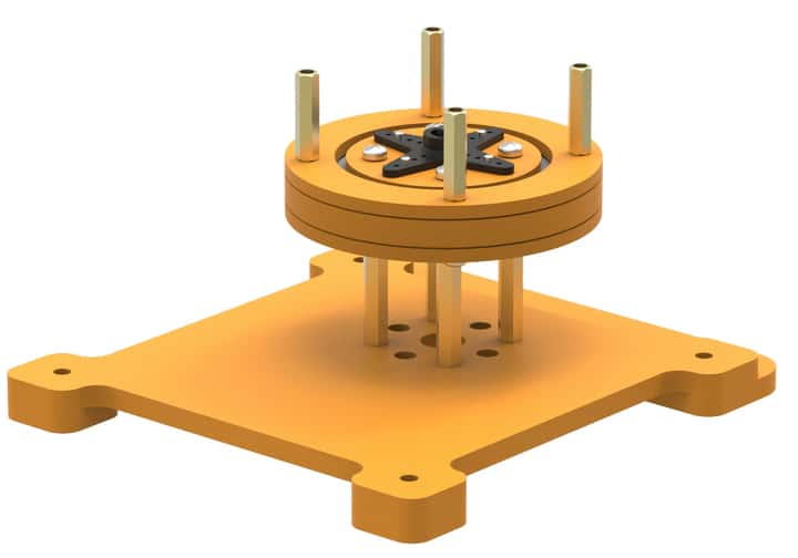
- Place 20 mm stand-offs on the top and fasten the M3 bolts of 20mm length from the bottom. Your base is completed now.


The base assembly should look like this upon completion.
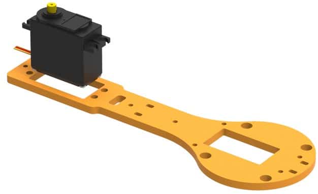
- Place servo motor into the slot available on racquet-shaped link 1. Be careful about the positioning and the orientation of the servo. Have a careful look at the illustrations.
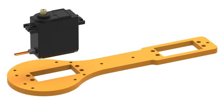
- Fasten the servo to the link using M4 bolts of 16mm length and nuts.

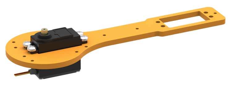
- In the figures, you see head of servo pointing upwards. Don’t let this confuse you; the head actually goes into the slot in the horn. We will come to this again, for now attach M3 bolts of 8mm length and 20mm standoffs to the link as shown in the illustrations below.
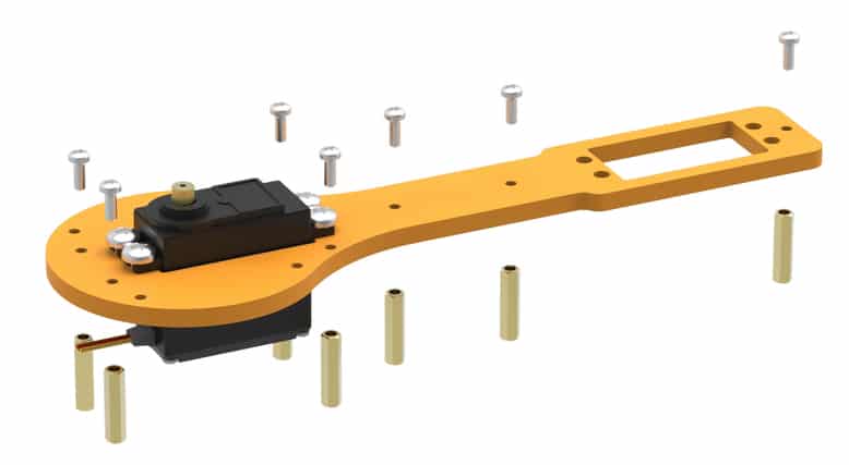

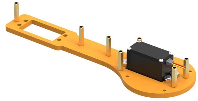
- Place this assembly on the base as shown & fasten using M3 bolts of 8mm length.
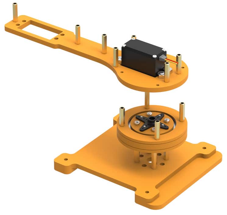


- Observe how head of the servo goes into the servo horn. We have to ensure proper locking between servo head and servo horn. To do this, drive a bolt into centre of the horn (find this in servo accessories) through the bottom of the base (through the large hole) and fasten it.
- Push the servo in the slot provided on the racquet shaped link 2 as shown and fasten it using M4 bolts of 16mm length and M4 nuts. Notice the difference between this step and what we did for the sketching robot.

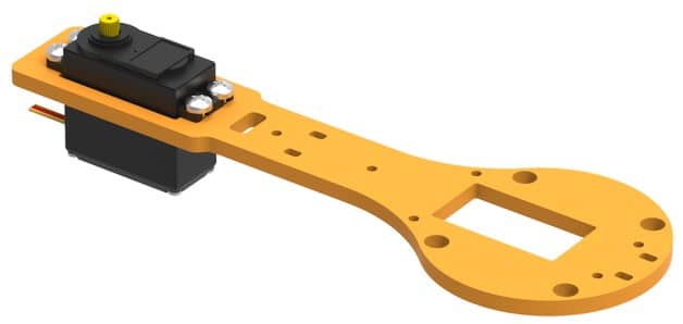
- Place this on the part you have already assembled (step 0) and fasten using M3 bolts of 8mm length.

This is how our first link will look once the Racquet-shaped links have been assembled. The head of the Servo points upwards.

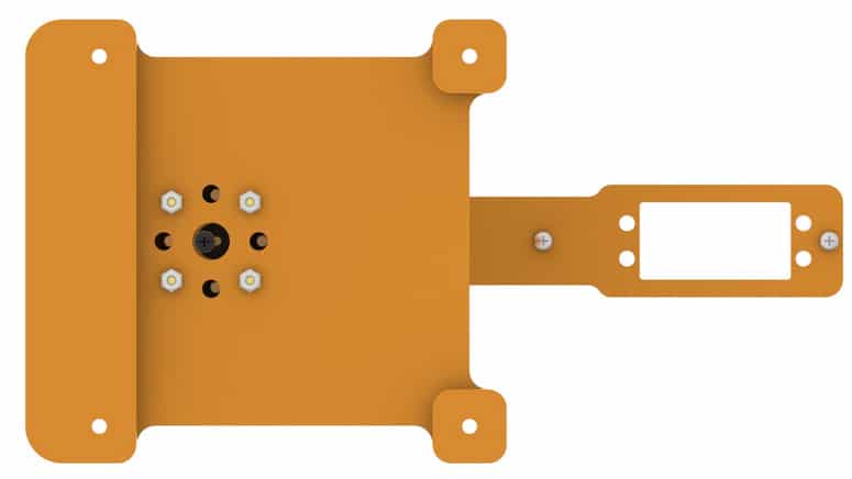
- Take the supporting link and attach a servo horn to it as shown. Fasten the horn with M2 bolts of 8mm length.


- Place the servo horn on Link 1 servo and fasten it using M3 bolt provided with the servo. You can also attach support link 2 if the robot arm is bending using M3 20mm stanoffs, M3 Bolts of 8mm lenght and M3 nuts.
Your assembly is complete
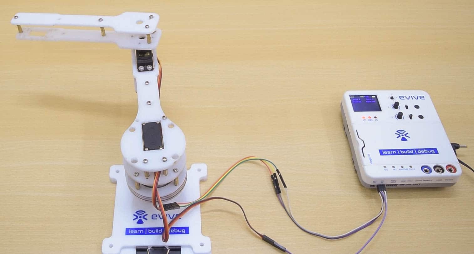
Controlling robot using evive
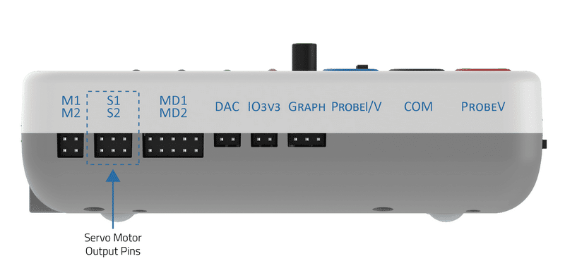
evive has two dedicated servo motor outputs pins.
Signal pin of servo 1 is connected to digital pin 44 and servo 2 is connected to digital pin 45.
Circuit Diagram
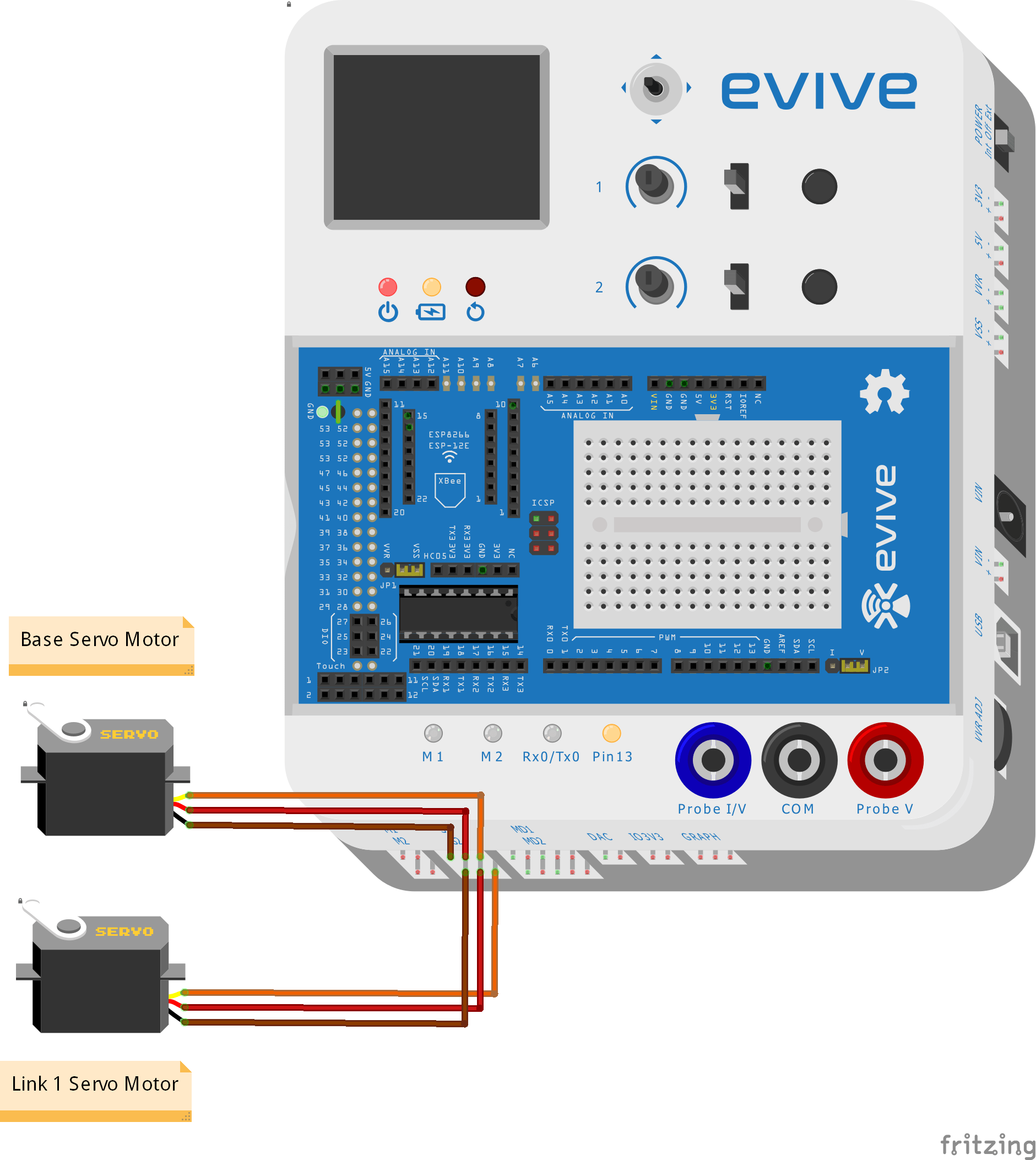
In the following example, I will be showing you how to control servo through channel 1 and channel 2. Given below is the circuit diagram:

A Servo pin has three wires (Order to be connected in evive, left to right)
- Brown wire: GND
- Red wire: VCC
- Orange wire: Signal
evive Firmware
- In the firmware, the first option is Control. Using the navigation key, click right and you will enter control submenu.
- In control submenu, you will find three options:
- Motors
- Servos
- Stepper Motor
Navigate to Servo.
- In side servo motor control you will see another three options:
- Servo 1 (To control servo motor through channel 1)
- Servo 2 (To control servo motor through channel 2)
- Servo 1 and 2 (To control both servo motor)
Select Servo 1 and Servo 2 for this case
- Now you will see a panel, where on the left half you see angle set on servo channel 1 and channel 2. Using Potentiometer 1 you can control the base servo angle ranging from 0 to 180 degrees and potentiometer 2 you can control link 1 servo angle.

Arduino Code
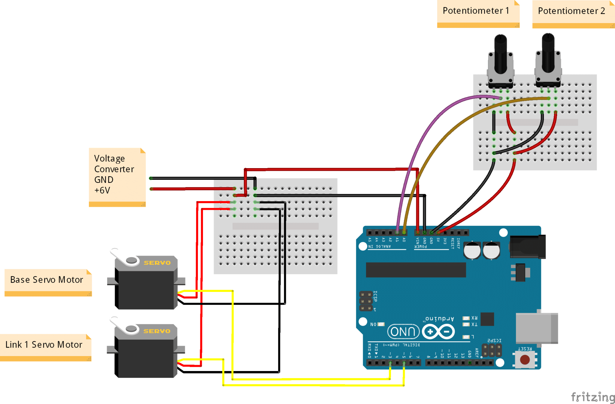
Controlling Arm using Arduino Uno
Arduino uno has 6 PWM pins: 3, 5, 6, 9, 10, and 11 which provide 8-bit PWM output with the analogWrite() function.
We will controlling serov using Pin 3 and 5.
Circuit Diagram
A Servo pin has three wires (Order to be connected in evive, left to right)
- Brown wire: GND
- Red wire: VCC
- Orange wire: Signal
Code


![[CODEAVOUR 2021] project demonstration video 4-12 screenshot](https://ai.thestempedia.com/wp-content/uploads/elementor/thumbs/CODEAVOUR-2021-project-demonstration-video-4-12-screenshot-q7ynxvlwjfsgj74xjev4cqopqur232if4hglkl3itk.png "[CODEAVOUR 2021] project demonstration video 4-12 screenshot")


