Introduction
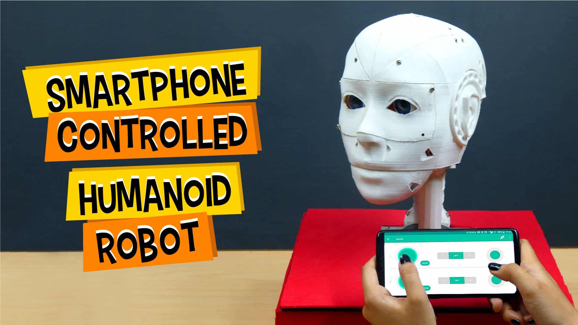
Many of you may know Sophia, a humanoid robot modeled after Audrey Hepburn, and the first robot citizen of the world. Today we’re going to make something like her: our own humanoid robot – Casper. He can look right and left, can turn his eyes, and move forward and backward; all of this with the help of only ONE app – Dabble, a smarter-than-the-phone project-making app.
We’re going to code him using PictoBlox – our powerful graphical programming software.
You can get Dabble on Google Play and download PictoBlox from HERE.
So, buckle up and get ready for an exciting project-making ride because this isn’t going to be like the other projects; it’s going to be challenging, fun, and full of next-level DIYing!
Overview of the Process
The entire process of making the Humanoid Robot will be divided into three steps: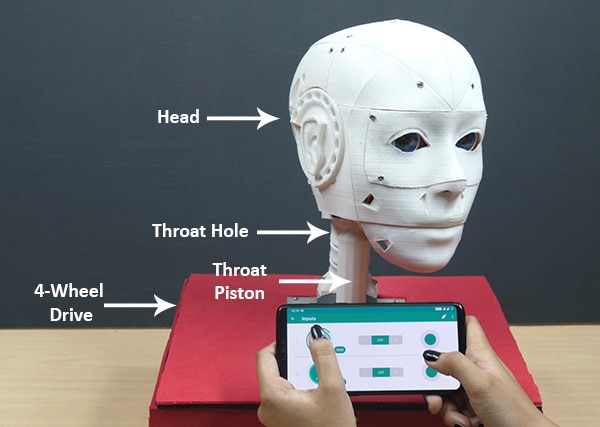
- Assembling of the Head, Neck, and Eyes
- Making of the 4-Wheel Drive
- Completing the entire assembly
We’ll try to look into each one of them in detail.

Assembling the Humanoid Robot
Fixing the Holder
- There are a number of components that you might need to 3Dprint or Lasercut. You can download the STL files from here and the MDF designs from here.
- We will be fixing the head of the robot on the MDF base plate or chassis. A number of holes are given on it to attach the 4-wheel drive robot and head to it.
- Now, take the 3D printed holder and fix it on the MDF sheet in the center of the sheet using M3 nuts and bolts of 25mm.
- Insert M3 nuts and bolts of 20mm length in the center holes.
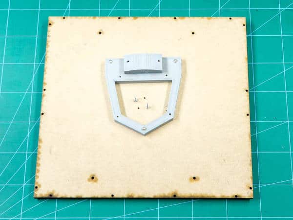
Thus, the assembly of the holder is complete.
Assembling the Throat
Let’s start the actual assembly now.
- Take the ThroatHole and fix it on the 3D printed holder that we have already attached on the MDF sheet using M4 bolts.
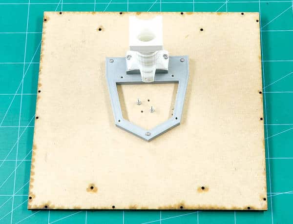
 We will build the smaller parts and keep fixing it on the ThroatHole assembly. Also, the wires of all the electronic components will pass through the ThroatHole.
 - Screw the MainGear to the NeckHinge using M4 bolts.
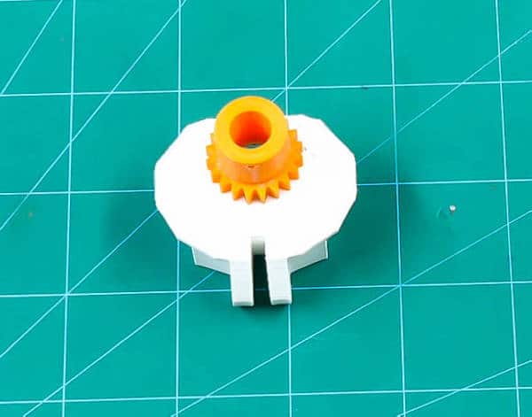
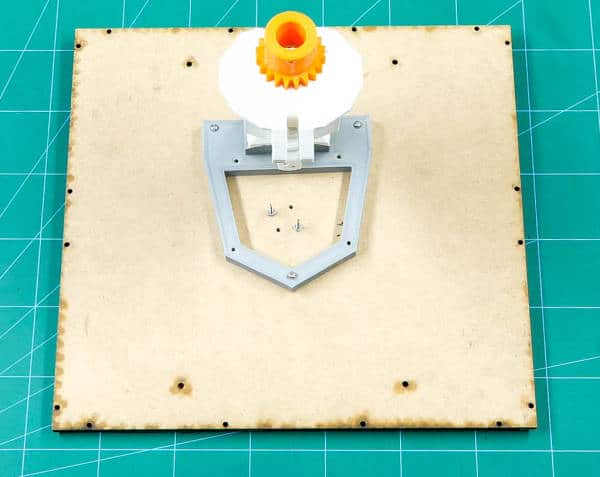
- As we already know, we will finally fix all the assembly on the ThroatHole. Fix the above assembly of the NeckHinge on the ThroatHole using a 3D printed connector.
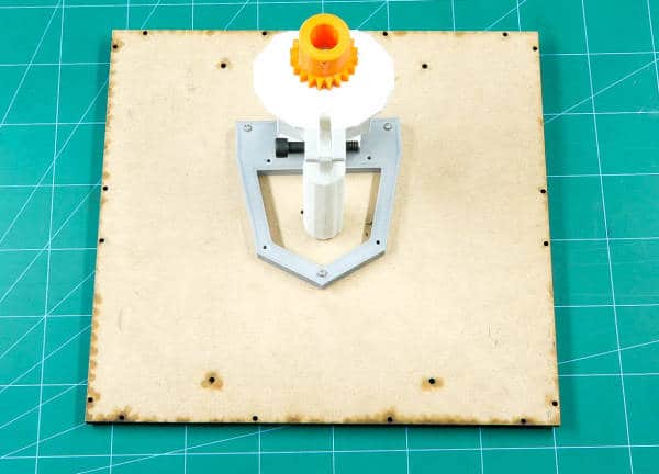
- Take the ThroatPiston, this will act as the support for the entire head. Fix the ThroatPiston in the NeckHinge using the black 3D printed connector. If you remember, there are three M3 nuts and bolts free in the center of the 3D printed holder. Thus, fix the ThroatPiston from its hollow space into it.
- Take the GearHolder and pass the ServoGear through it. Screw the actuator wheel to it using self-threading screws.
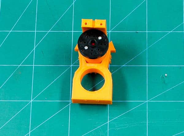
- Fix this GearHolder assembly to the ThroatHole assembly using M4 bolts. Take the Ring and screw it to the MainGear using M3 bolts.
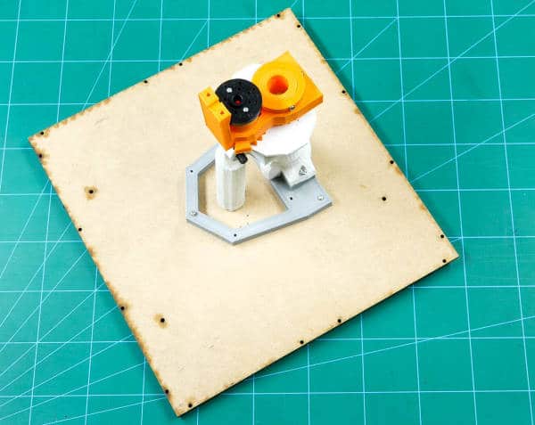
- Fix the LowBack(V3) onto the GearHolder using M3 bolts.
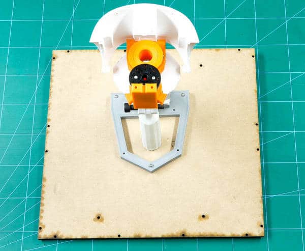
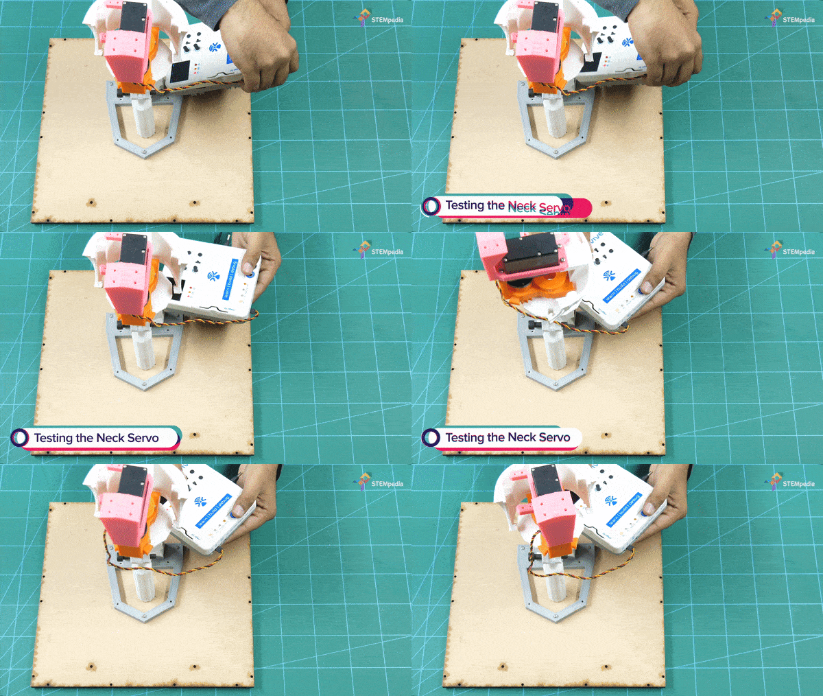
- Take the HS-805BB servo(neck servo) and calibrate it using evive and set the angle to 90º. You can do this with the help of evive firmware. Go to evive menu, choose Controls, select Motors, then select Servos, select Servo1, and now you can set the angle using Potentiometer 1.
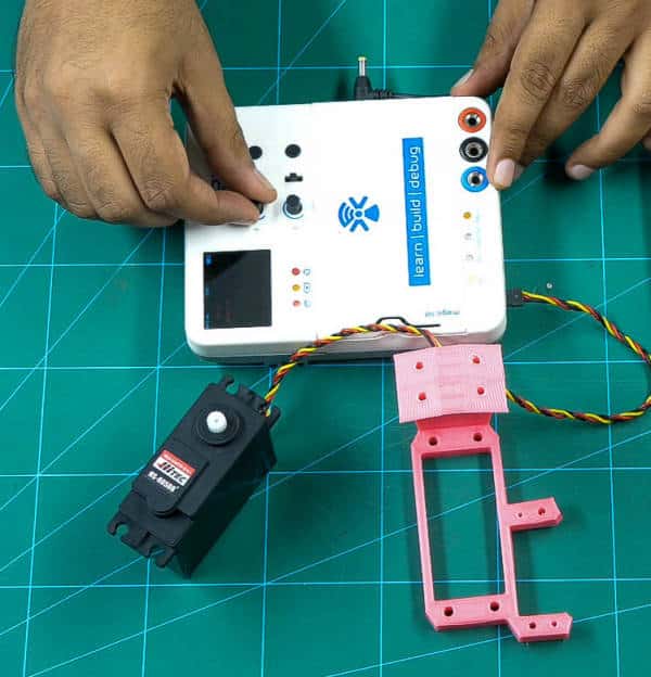
- Fix the servo into the SkullServo Fix using M4 bolts.
- Fix the SkullServoFix onto the space given in the LowBack using M3 nuts and bolts. Also, make sure that the servo head fixes in the Rotation wheel.
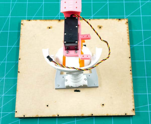
 Check the rotation of the head once with the help of evive’s firmware.
Assembling the Jaw
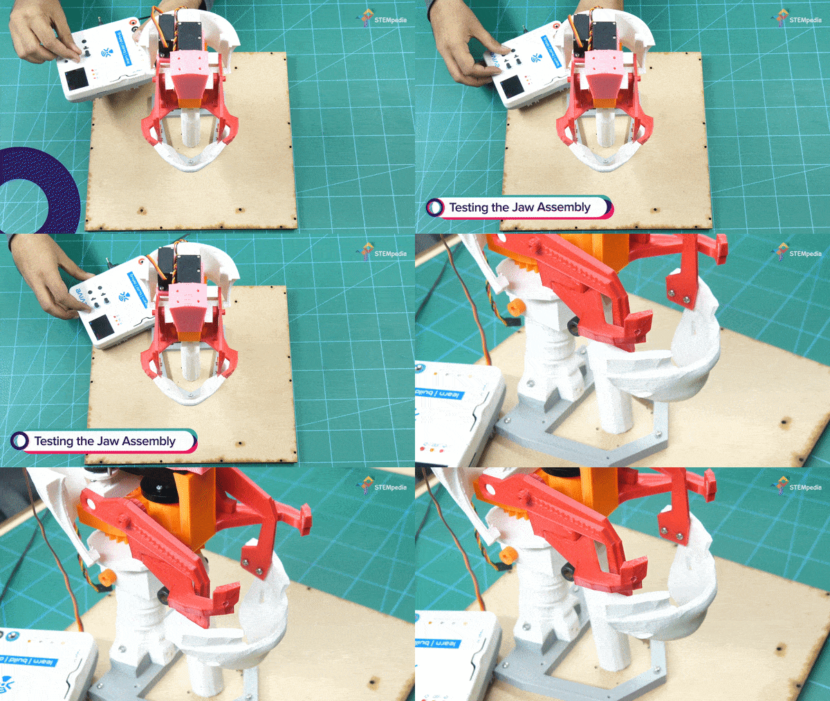
- Take a metal servo and fix Jaw Piston on it using the self-threading screw.
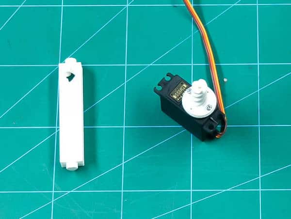
- Push the JawHinge through the JawPiston.
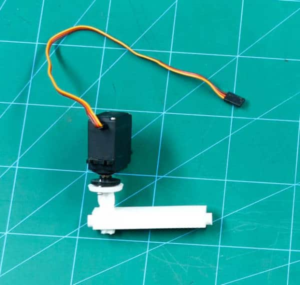
 Calibrate the servo(jaw servo) by setting the angle at an angle such that JawHinge should slip out. For us, we have set the set at 65°
 - Fix this JawPiston assembly onto the SkullServoFix using M3 Nut.
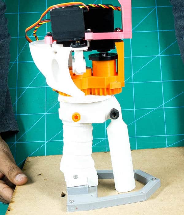
- Take the two FaceHolders and fix each in the slot given on the GearHolders on both the side.
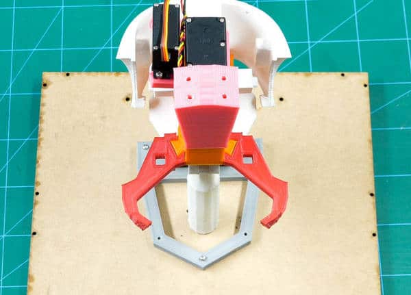
- Fix both the JawHinge(V3) on both the FaceHolders.
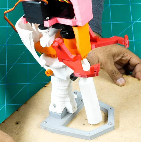
- Take the Jaw(V4) and fix the JawSupport(V1) to it using M3 bolts.
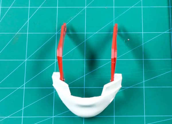
- Fix the Jaw assembly into the JawHinge on both sides.
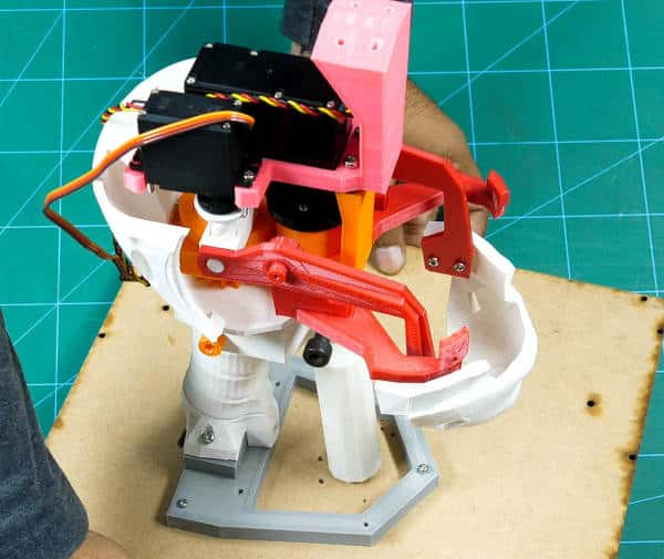
 Check the movement of the jaw by connecting the metal servo(jaw servo) to the evive and control it using evive’s firmware.
Assembling the Head
- Take the two TopBackSkull(V1) and fix it on the LowBack using M3 nuts and bolts.
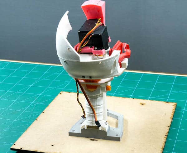
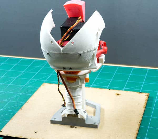
- Take TopSkullLeft(V3) and TopSkullRight(V3) and fix them together using M3 nuts and bolts.
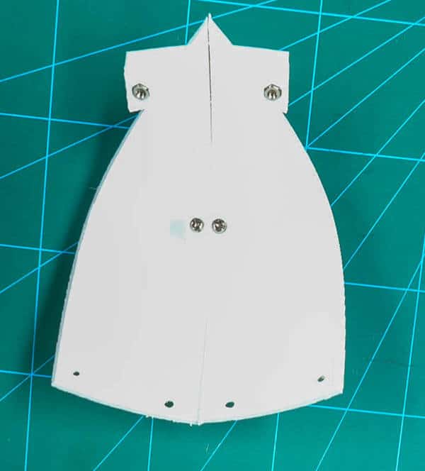
- Fix these parts into the SkullServoHolder using M3 nuts and bolts.
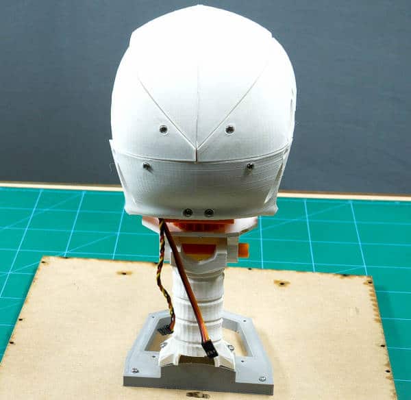
- Take the other TopSkullLeft(V3) and TopSkullRight(V3) and again fix them together as we did for the previous part. Fix them to the assembly made.
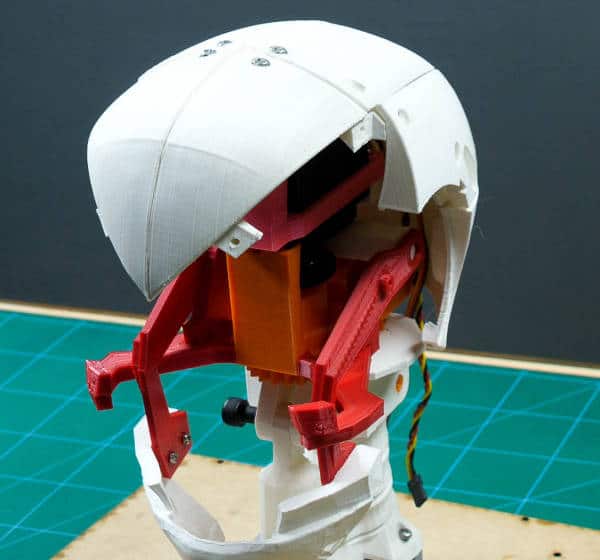
- Take the other two TopSkullLeft(V3) and TopSkullRight(V3) and fix it next to the assembly made using M3 nuts and bolts
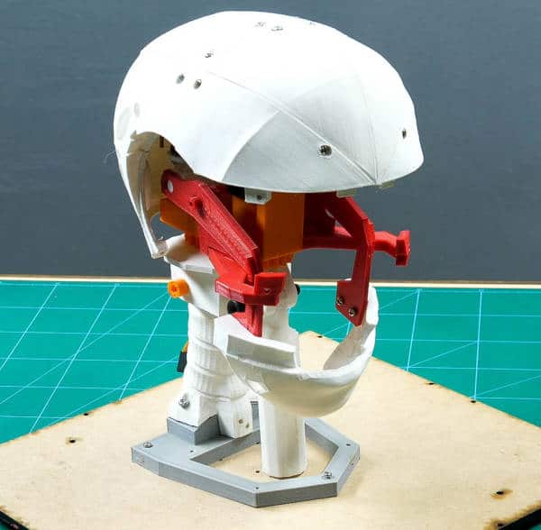
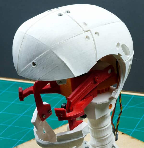
- Fix the SideHear(V3) and fix it next to the TopSkullRight using M3 nuts and bolts.
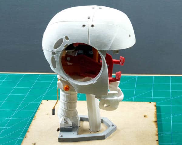
- Fix Ear into the SideHear using the slot given.
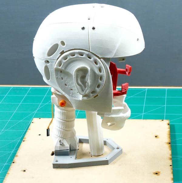
- Similarly, repeat for the other side.
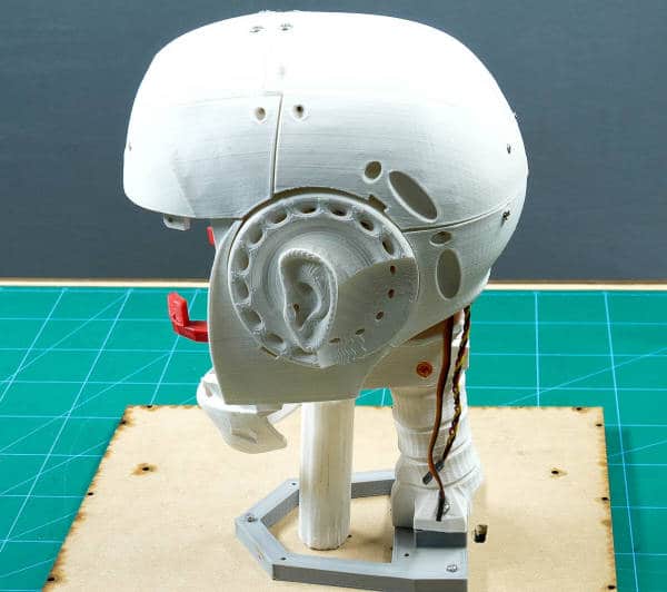
- Fix the TopMouth(V3) next to the TopSkullRight and TopSkullLeft using M3 bolts.
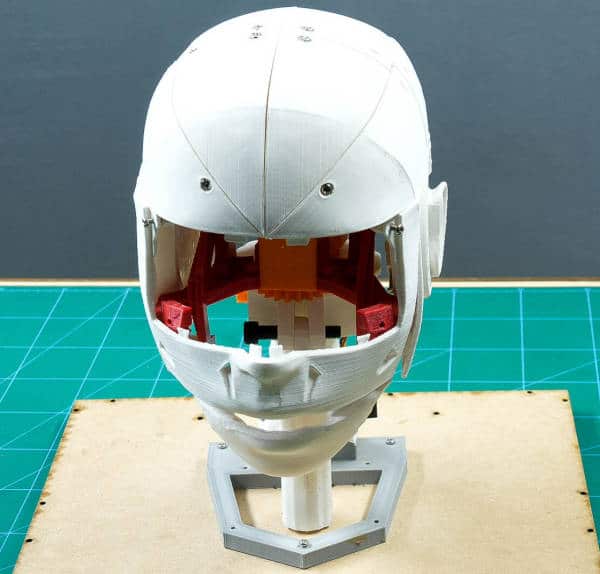
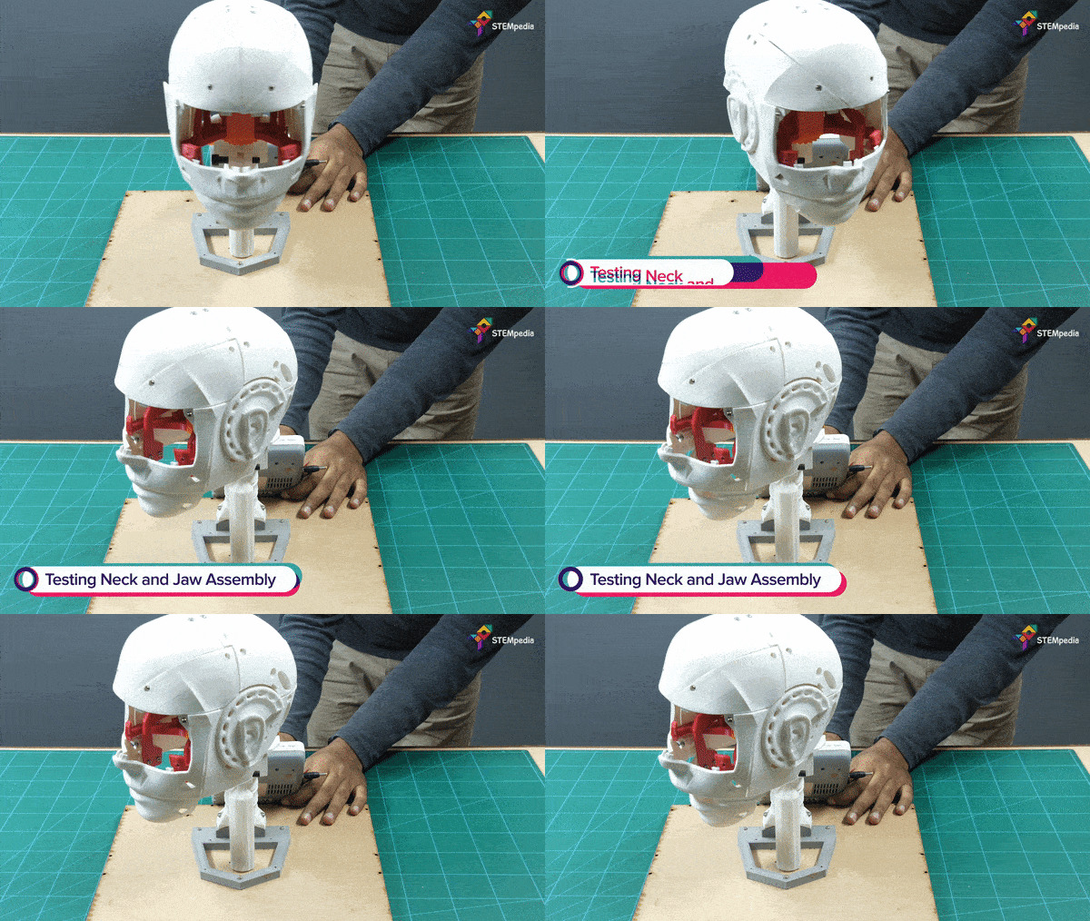
 Check the movement of the jaw using evive, this time you may notice that it seems that the head is now talking.
Adding the Eye Mechanism
We already have the entire eye mechanism with us. You can make the complete assembly from the website of InMoov.
- Take the eye mechanism and the EyeGlass(V4). You may notice a small part on the back of the Eyeglass. This is where we can fit the eye mechanism using M3 nuts and bolts.
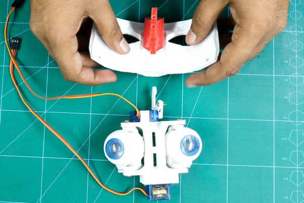
- Check the micro servos(one will make the horizontal movement and the other will make the vertical movements) of the eye using evive and bring the eyeballs to the center.
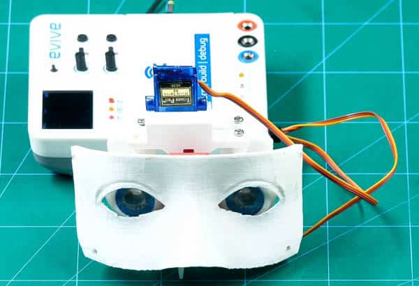
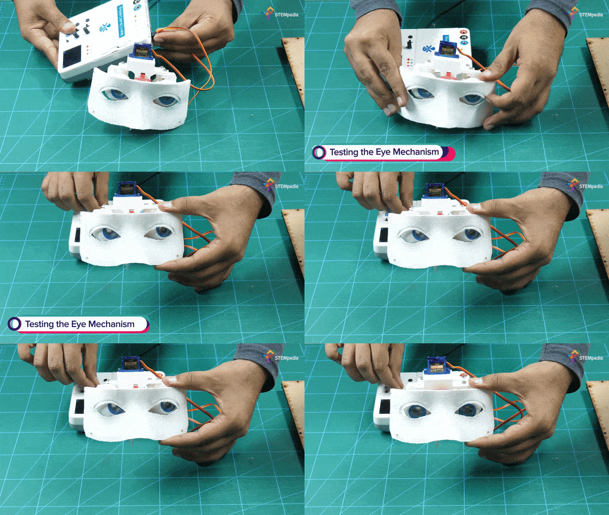
- Now take the TopMouth out of the assembly and fix the EyeGlass to it using M3 nuts and bolts.
- Finally, fix this in the head.
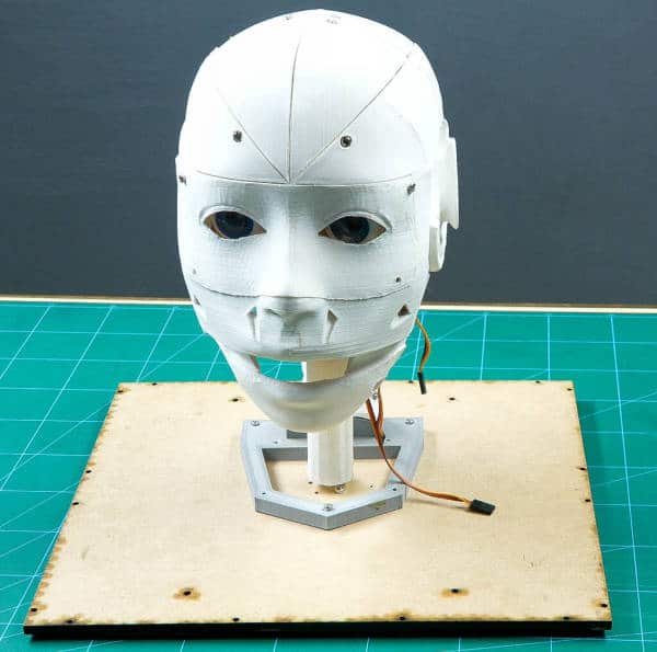
Yay! Thus your head is ready. Now’s its time to make it move
Assembling the 4-Wheel Drive
- Insert 12mm screws to the motor brackets. Attach the DC Motor of 100rpm to it. Similarly, attach the other 3 motors to the brackets too.
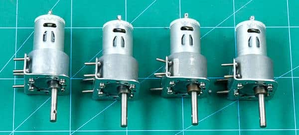
- Attach wheels to the motor shafts and fix it using screws.
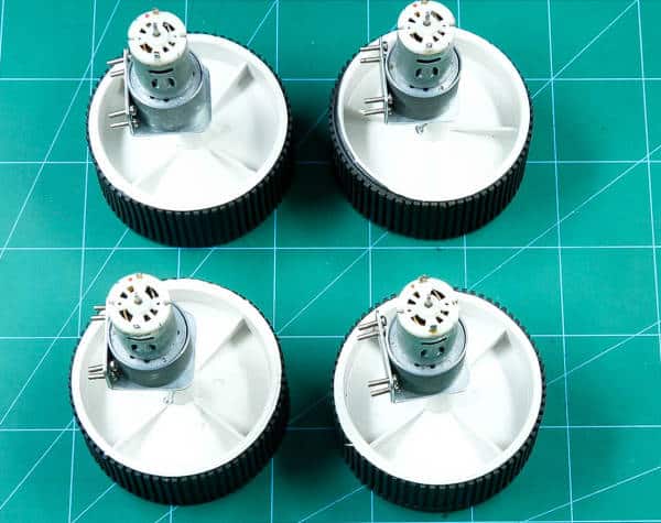
- Take the base plate or chassis and you may notice that there places to fix the wheels. Take the wheel and fix the motor brackets to it using the M3 nuts and bolts.
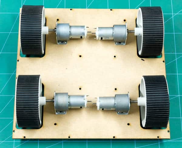
- Now, we need to attach wires to the motors. Take the connecting wires and add solder it to the motors using a soldering iron and soldering wire.
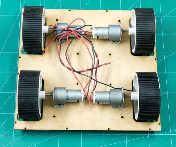
- Take the side wall and attach the motor driver to it using M3 nuts and bolts. Attach the side wall to the base plate using M3 nuts and blots. Attach wires of the motors of one side to this motor driver.
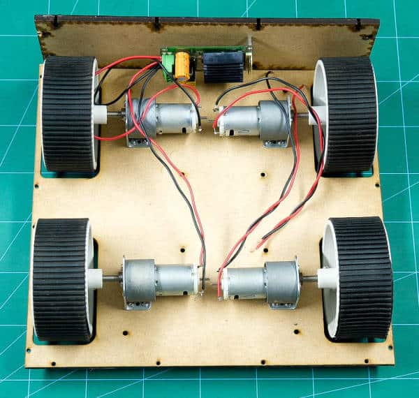
- Similarly, connect the motor driver on the other wall. And add connect the wires of the motors of the other side to this motor driver.
- Fix the front and the back walls.
- We will add a switch to power up the Robot. Thus, fix the switch to one of the walls.
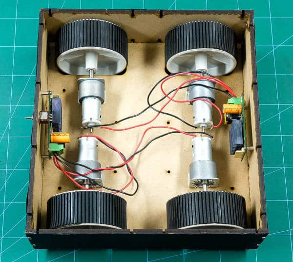
- Once done, make the VCC and GND wire common for both the motors of one side.
- Now its time to bring evive. Make the connection as given in the connection section.
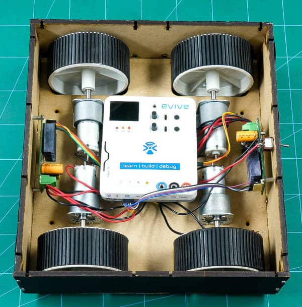
- Also, to power up the robot, we need to add the battery. Take a LiPo Battery and connect it via the power switch.
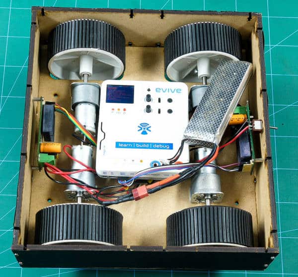
 Before uploading the final code to evive. Test the motors using evive’s firmware.
 - Once done, upload the code to evive.
Completing the Assembly
- Bring the robot head and make the connections of all the servos to the evive as given in the below section.
- Fix the head on it using M3 bolts and nuts.
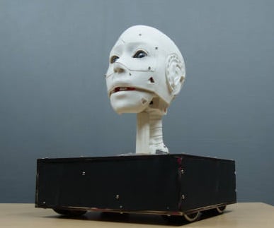
Thus, your humanoid robot is now ready.
Making the Connection
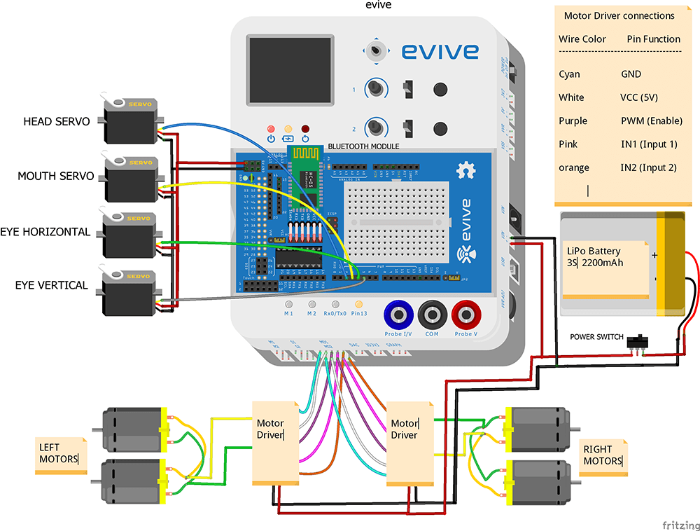
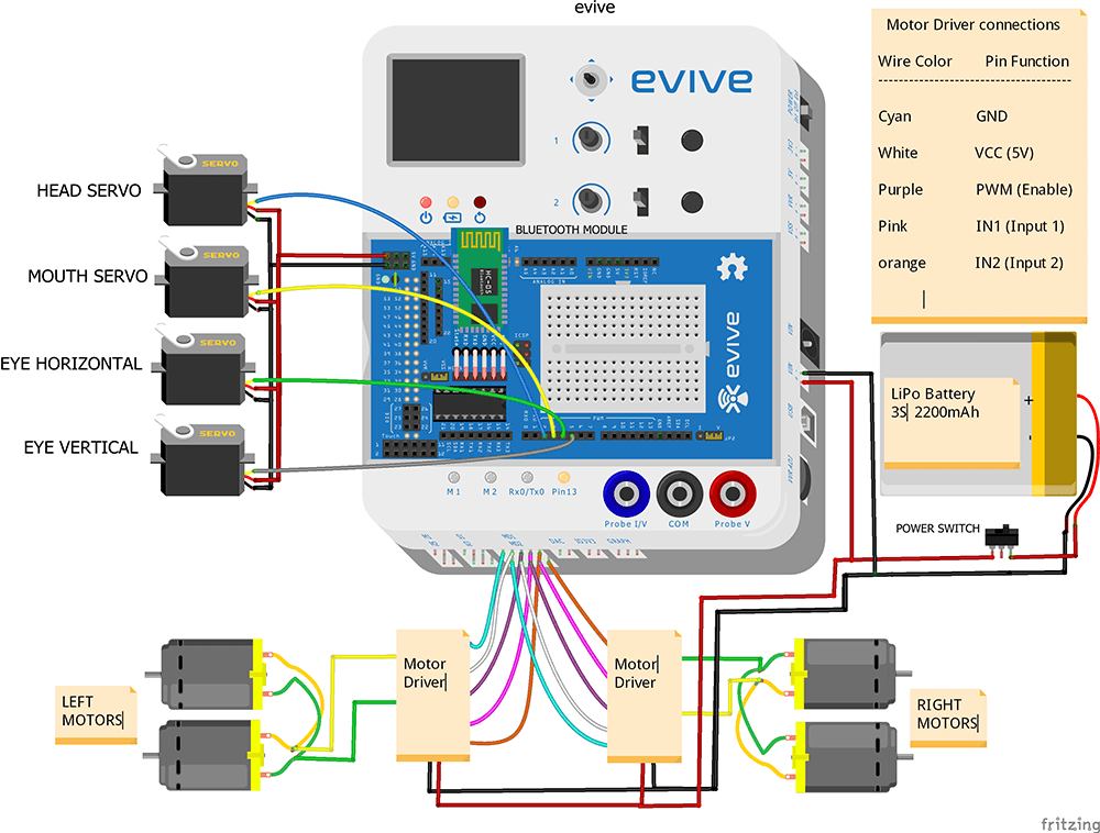
Let’s first connect Motors to the Motor Drivers
- Connect both the motors of the left side parallelly.
- Connect both the motors of the right side parallelly.
- Connect one end of the left motor to one of the motor output terminals(OUTA1) of left motor driver.
- Now connect the other end of the motor to motor output terminal (OUTA2) of the left motor driver.
- Similarly, do it on the right side.
- Now connect the VCC and GND of both the motor drivers together.
- Take the slide switch and connect its one end to the positive terminal of the battery and its other end to VCC terminal of the motor driver.
- Connect the negative terminal of the battery to the GND terminal of the motor driver.
Bluetooth Connection with evive
- Connect HC-05 Bluetooth module in the given place
Connection of Motor Drivers with evive
- 1)Connect the positive and negative terminal of a battery to the VIN port on the evive.
- 2) Connect VCC, GND, PWM, IN1, and IN2 pins of the left motor driver to MD1 port on evive as shown in the figure.
- Similarly, connect VCC, GND, PWM, IN1, and IN2 pins of the right motor driver to MD2 port on evive.
Finally, connect the face servos with evive
- 1) Connect (HS-805BB Servo or Head Servo) Signal pin to pin number 2 of evive
- 2) Connect (Metal Servo or Mouth Servo) Signal pin to pin number 3 of evive
- 3) Connect (micro Servo or eye Horizontal Servo) Signal pin to pin number 4 of evive
- 4) Connect (micro Servo or eye Vertical Servo) Signal pin to pin number 5 of evive
- 5) Connect the VCC and GND of all the servo motor together and connect it to the VCC and GND of evive respectively.
Working of the Robot
The HC-05 Bluetooth module is used to connect our Humanoid Robot to Dabble. Install and open Dabble and click on the Connect-Disconnect button.
On the Bluetooth of your Smartphone and choose your device’s name from the list.
Here, we are going to use two modules together:
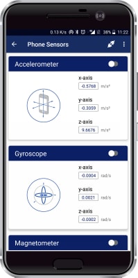
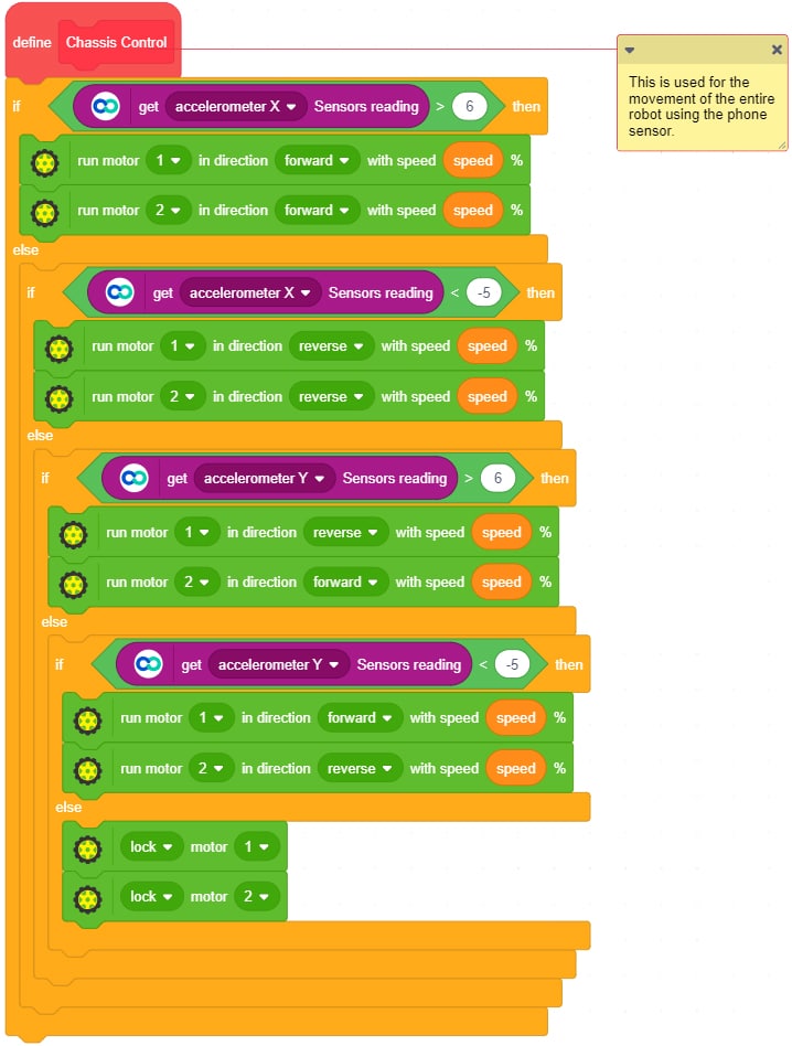
The DC motors are used for the movement of the robot which is controlled by the Accelerometer module. Open Phone Sensors and click on the toggling button next to the Accelerometer. This will start sending data to evive. Thus, When we tilt the phone either forward or backward, acceleration along the X-axis changes.
- If the acceleration along X-axis goes above 6 m/s2, then the robot will move in the forward direction.
- If it goes below -5 m/s2, then the robot moves in the backward direction.
- If we tilt the phone either left or right, acceleration along with the Y-axis changes.
- If the acceleration along Y-axis goes above 6 m/s2, then the robot moves in the left direction.
- If goes below -5 m/s2, then the robot will move in the right direction.
- If the acceleration along both the axes i.e X-axis and the Y-axis is between -6 m/s2 and 6 m/s2, then robot does not move.
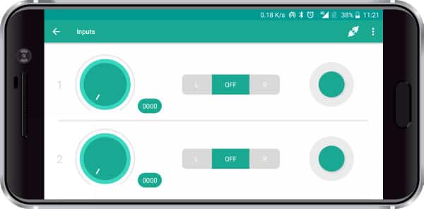
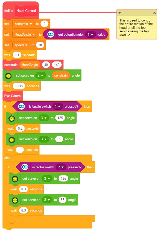
The HS-805BB servo is used to control the movement of the head i.e. from right to left and vice-versa. We can control it from the Potentiometer 1 of the Input Module.
The metal servo is used to control the movement of the Jaw. We can open and close the jaw using the Tactile switches of the Input Module.
- Tactile switch 1 is used to open the jaw for a longer duration.
- Tactile switch 2 is used to open the jaw for a shorter duration.
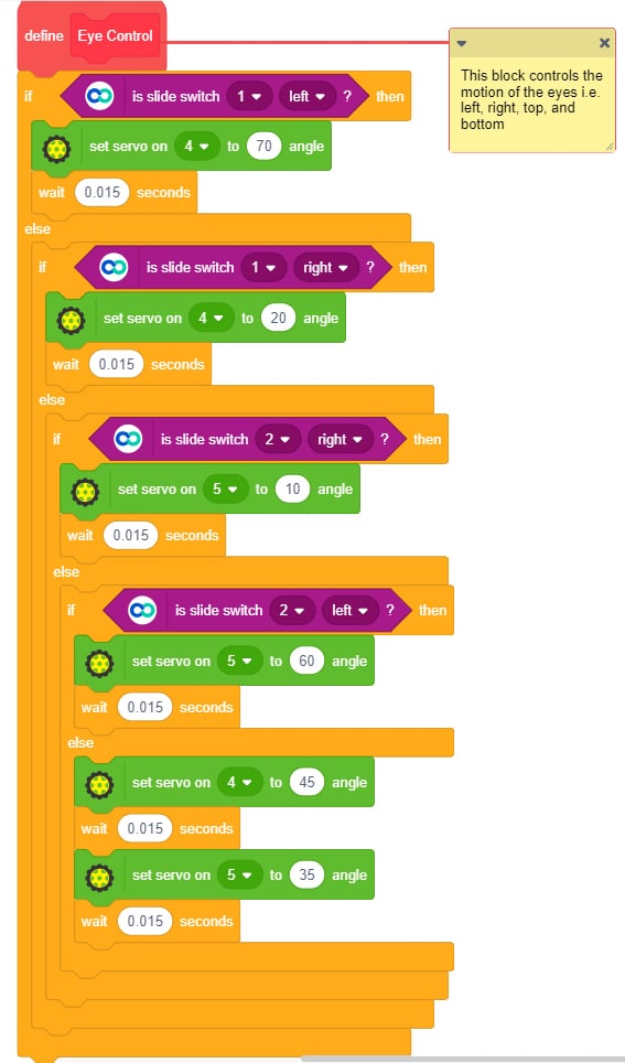
The two micro servos are attached in the eye mechanism. They can be controlled using the Slide switches of the Input Module.
- Slide Switch 1 is used for the horizontal movement of the eye i.e. left and right.
- Slide Switch 2 is used for the vertical movement of the eye i.e. up and down.
Writing the Code
Write the following code in PictoBlox: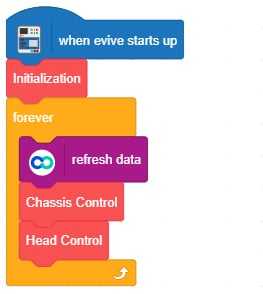
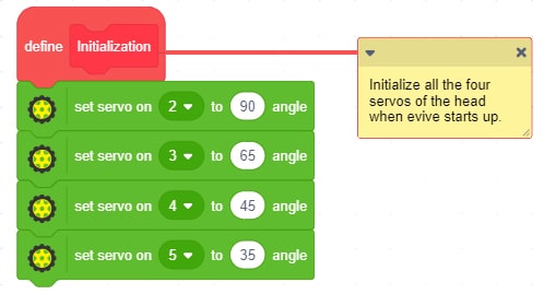
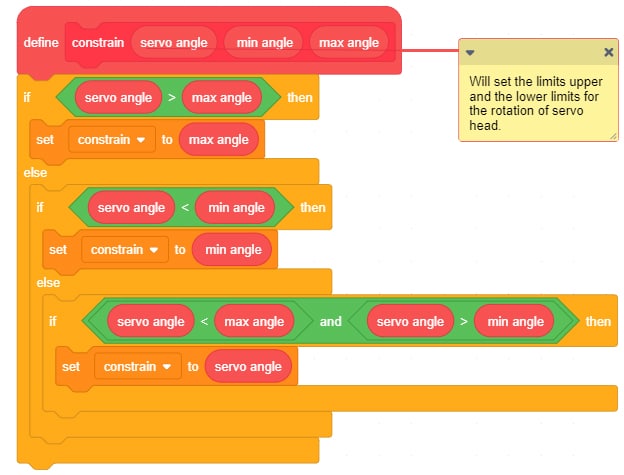
Conclusion
With this, your robot is ready! Have fun showing it to your friends as they stand there and look at it with awe!

