Introduction
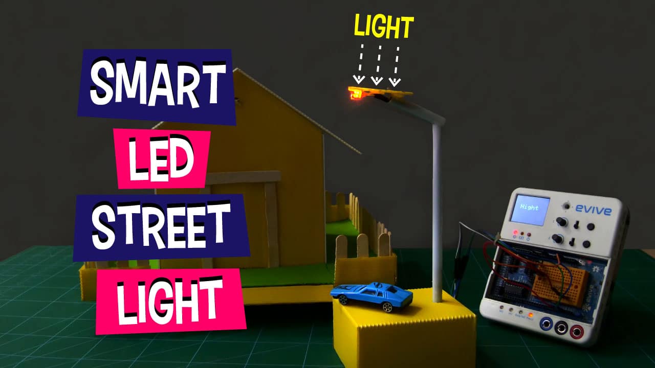
The DIY LED street light project is yet another easy yet fun to make the project for kids to gain knowledge with DIY. They can learn a thing or two about LDR working and application and coding while making this project. All that is required to make the smart street light is a few components from the evive Starter Kit, other DIY material, and the excitement to learning something interesting!
We’ll be writing the code for the project in PictoBlox – our Scratch based graphical programming software with advanced hardware interaction capabilities. You can download PictoBlox from HERE.
Ready for some learning by doing? Let’s get started!
Making the Base
- Let’s start by making the base for our LED street light. The base will be used to fix the pole in one place.
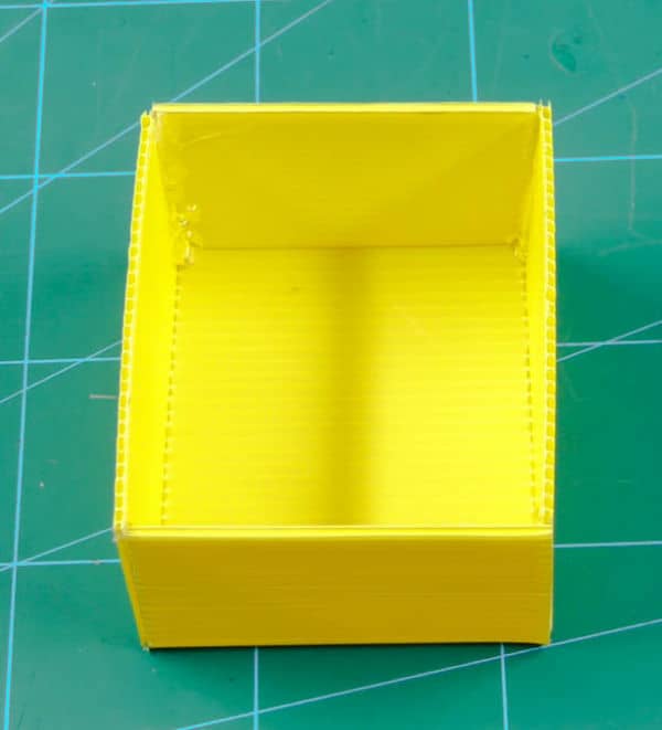
- The base for our automated street light will be of 10cm * 8cm * 5cm size box.
- Take a corrugated sheet of the size 20cm*20cm.
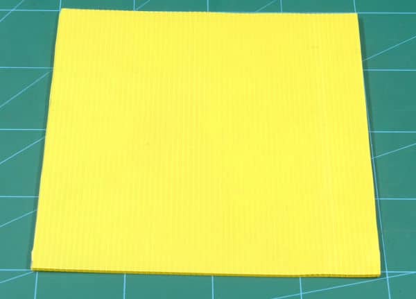
 You can use normal cardboard to make the base instead of the corrugated sheet.
 - It would be easier to first do the markings for box on the sheet. Make a rectangle of 10cm*8cm in the center of our sheet.
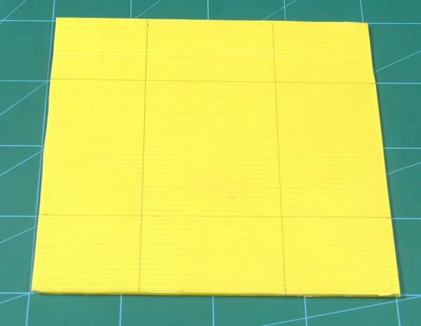
- Remove the corners so that your sheet looks like a plus sign, similar to the one shown in the below image.
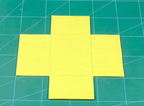
- You will notice that the two side edges out the four edges are 1cm bigger, trim those 1 cm out making it equal from all sides.
 Keep one of the corners for making the head portion of the street lamp.
 - Fold along the markings done using a ruler.
- And finally, glue them together using hot glue.
- With this, your base is completed.
Testing the LDR
- Before we use the LDR, let’s first test whether it’s working fine or not.
- To test the LDR, we are going to use the Pin State Monitor feature of evive as we can see the status of both analog and digital pins directly, which gives it an edge over Arduino.
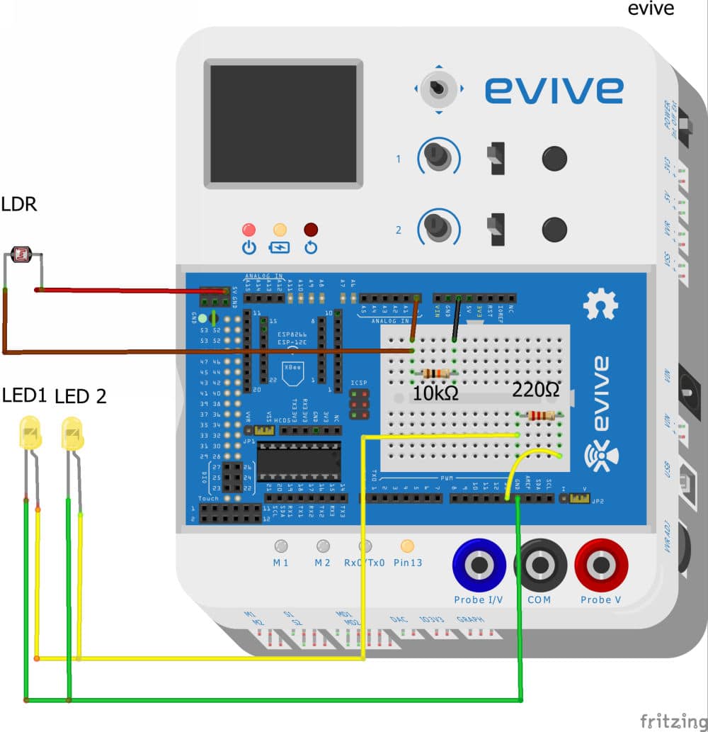
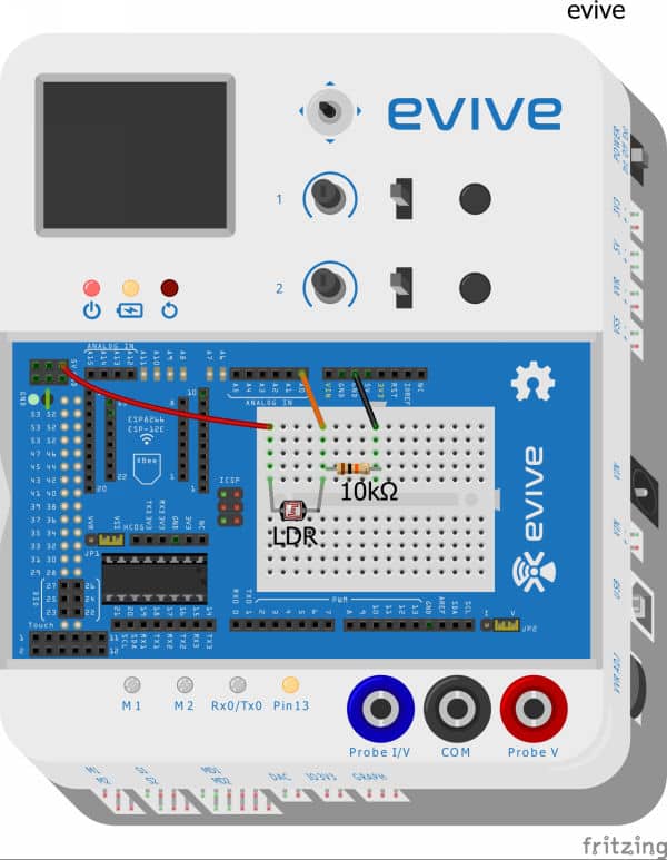
- Connect LDR with evive as given below:
- Firstly insert a 10k Ohm resistor in one of the pins of breadboard on evive.
- Then insert LDR into the breadboard such that the last leg of the resistor and the first leg of the photoresistor are in the same column.
- Then, connect the free leg of the resistor to the GND of evive.
- And the free leg of the photoresistor to +5V of evive.
- Finally, connect the common column to Analog Pin 0 of evive using a male-to-male jumper cable.
- Once the connections are done, switch evive ON.
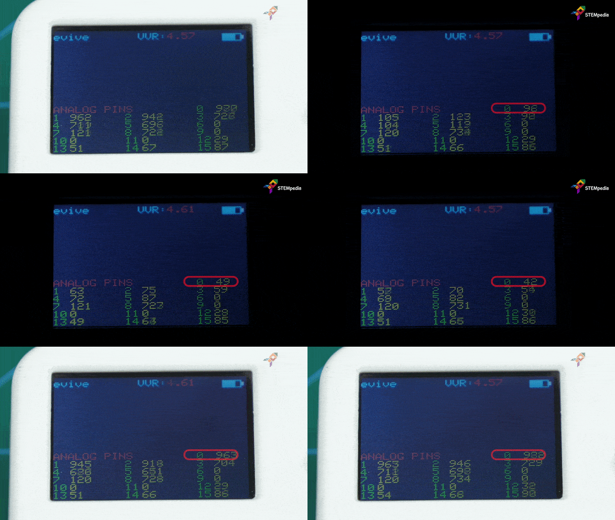
- Select Pin State Monitor from the firmware. As we have connected our LDR to Analog Pin, select analog pin states from the options.
- Now observe the value in front of 0. You may see that the value increases when the light is ON and it decreases as soon as the lights are OFF (intensity of the light decreases).
Making the Head of the Street Light
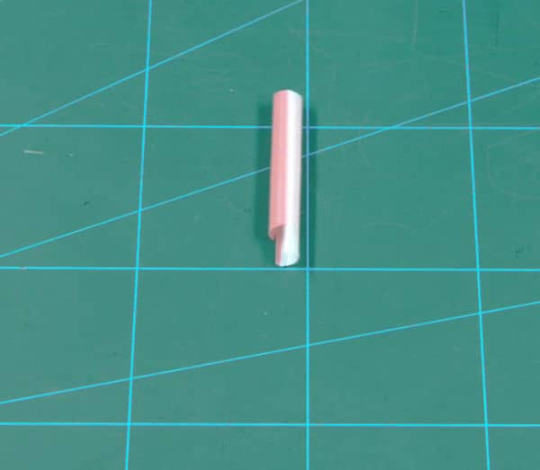
- We are going to use straws for the same purpose.
- Cut a small portion of the straw to make the arm. Make a slit of approximately 1cm at one end of it. This will help fix our head to the pole.
- To make the housing for our LDR and LEDs, we will need a small piece of the corrugated sheet.
- Thus, cut out a small U-shaped piece. Now, it’s time to bring our main elements into the picture.
- Create two holes into the U-shaped corrugated sheet or the lampshade of our Smart Street light using the header of the male jumper cable.
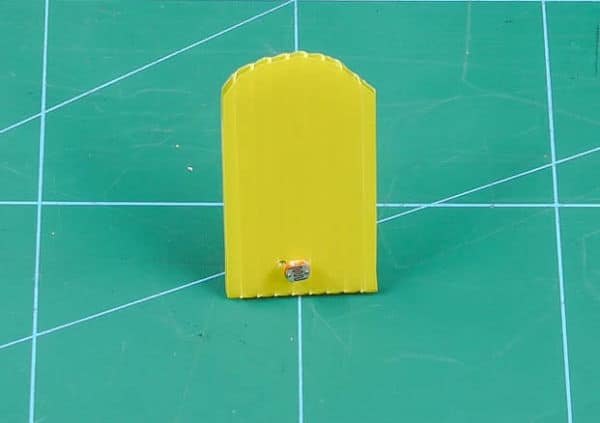
- Insert the LDR legs into the given hole so that it sits tightly on the top of our lamp.
- Connect the legs of LDR with a jumper cable and pass the wires through the arm.
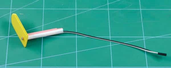
- Now, it’s time to add the LEDs of our LED Street Light. Attach the LEDs to the other jumper cable.
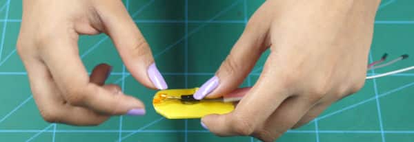
 Make sure to connect them parallelly.
 - Once done, glue the LEDs to the base of the head using Hot Glue and pass the wires to the arm.
Creating the Pole
- For making the pole of our smart street light we would use another straw. Try and use a straw with a large diameter for accommodating our jumper cables.
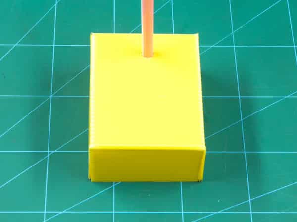
- Take the straw and mark its dimension on to the base by a pencil.
- By using a cutter create the small hole for our straw to fit in lightly.
- Use hot-glue from the other side to fix the pole.
Completing the Assembly
Now, let’s complete the assembly of street light by connecting all the parts.
- For connections, we would need to extend the jumper cables.’
- Now after extending the wires lets pass it through the pole.
- Grab them from below the base and connect as per the connections have given with evive.
- Finally, glue the arm or the head of the smart street light to the pole using hot glue.
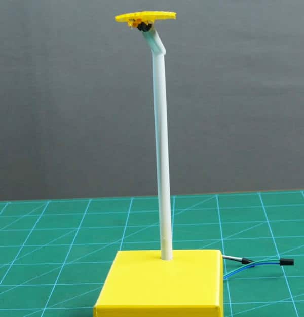
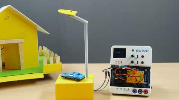
Connections
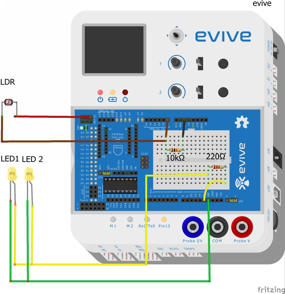
For final connections –
- Place a 220Ω and 10kΩ resistor on the breadboard.
- Connect +ve of led to the one end of 220Ω resistor.
- Connect -ve of led to the GND on evive.
- Connect one end of LDR to +5v on evive
- Connect one end of LDR to 10kΩ resistor
- Connect another end of the 10kΩ resistor to GND
- Connect A0 on evive with the common of LDR and resistor this would create signal by using a voltage divider circuit.
Writing the Code
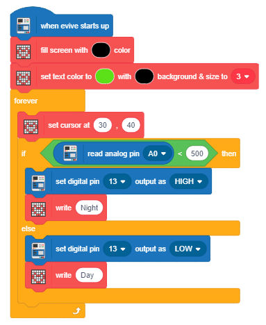
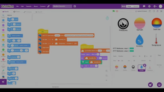
Write the following script in PictoBlox and upload it to your board:
The program will start executing as soon as evive starts up. The TFT display of evive will show the status of the surrounding light.
The LED connected to Digital Pin 13 should turn ON as soon the reading from the LDR i.e on the Analog Pin 0 is less than 500 and should turn OFF as soon as the value exceeds 500.
Conclusion
With this, your smart street light is ready! Hope you enjoyed making it.

