
Introduction
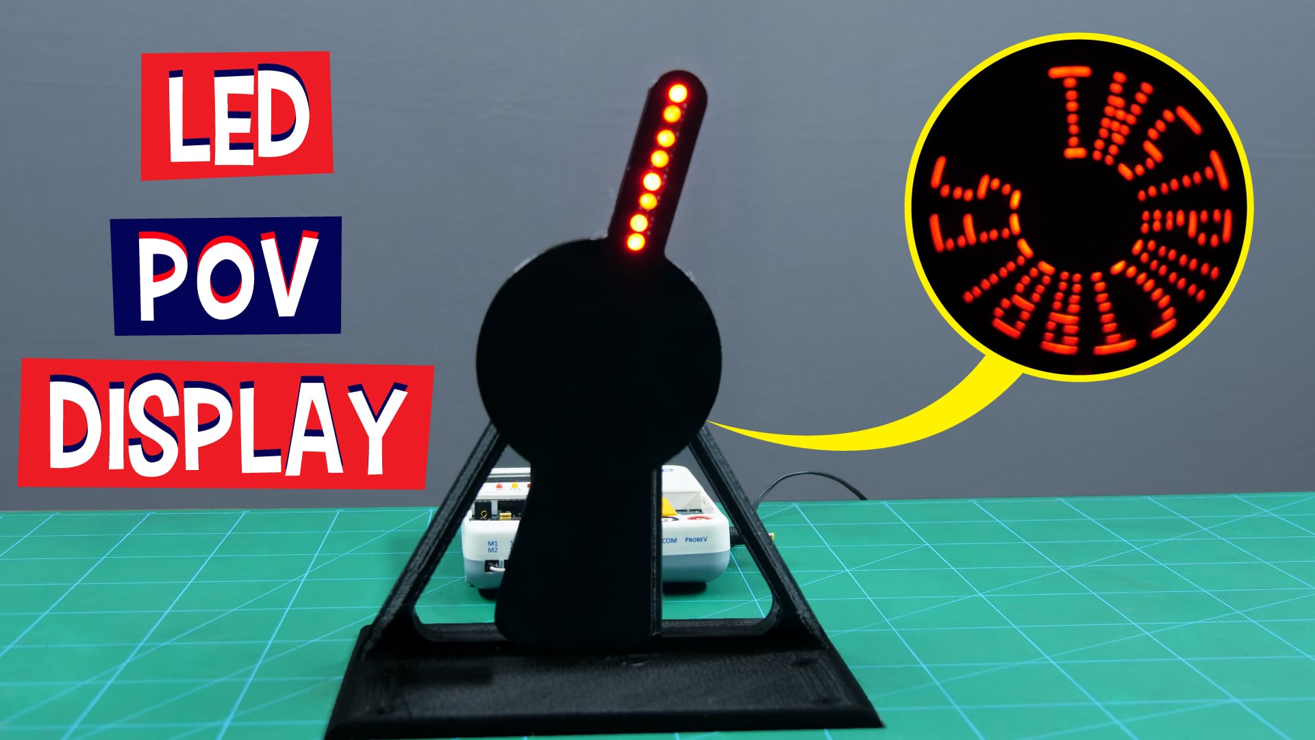
If you’re a fan of illusions, LEDs, and fun-filled DIY, then this project is for you. In this project, we’re going to show you how to make a cool and easy-to-make LED POV Display. POV stands for persistence of vision. It is a kind of optical illusion where a visual image seems to persist even when the rays of light from it cease to enter our eyes which makes it awesome! You can display any text or image that you want to with it.
Sounds interesting, right? So, what are you waiting for?! Let’s get started!
What is POV?
Persistence of Vision, or POV, occurs when a visual image seems to persist continuously when a stream of light is repeatedly interrupted for very brief instances and does not enter our eyes during those durations.
How Does POV Work?
The human eye cannot process more than 10-12 images per second. When a series of images more is presented in quick succession, it gives us the illusion that the images are in motion.
This is the basic principle behind the making of the animated movies.
Making
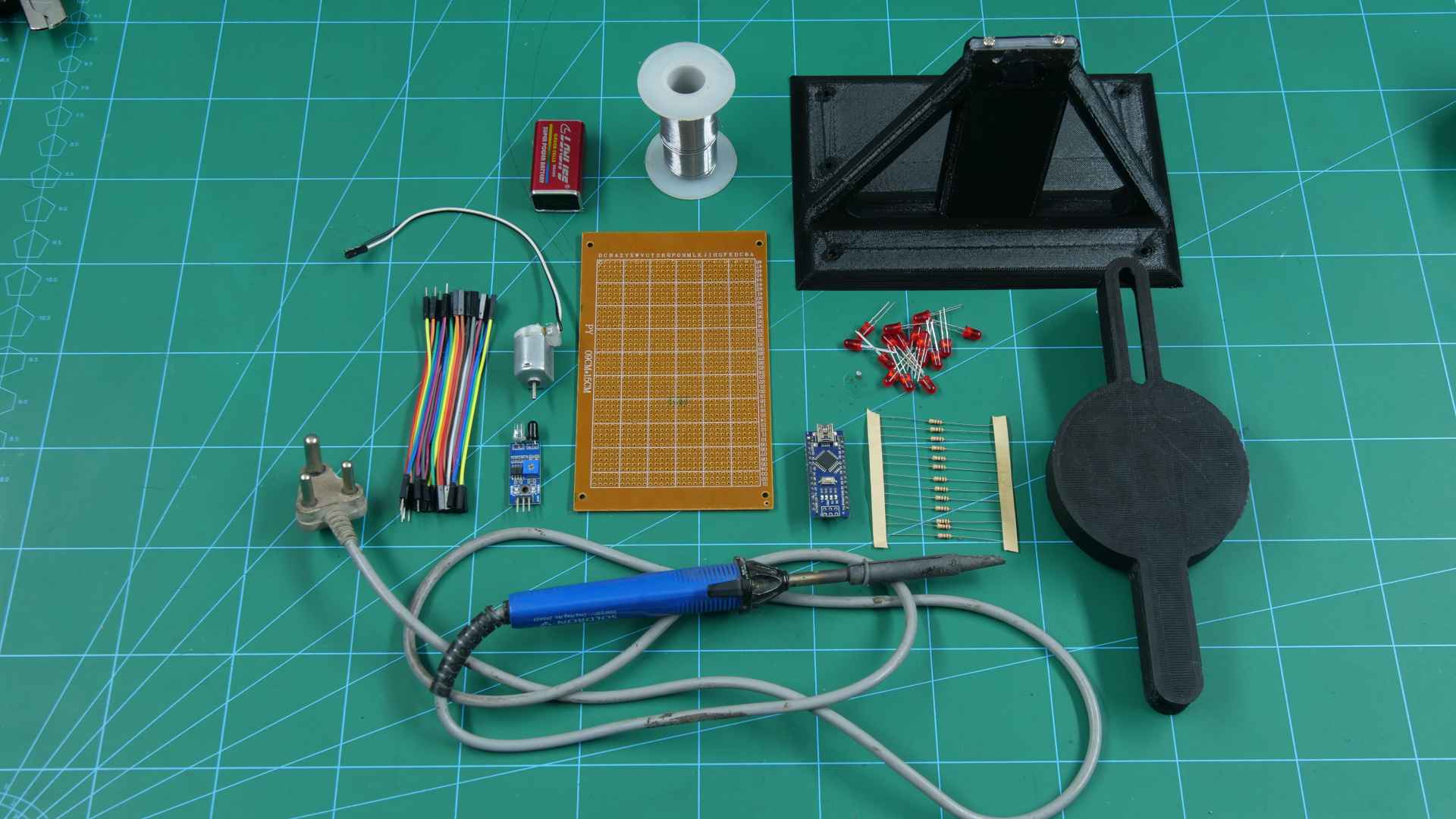
For making the LED POV display, we are going to use Arduino Nano, a General Purpose Board, some LEDs, an IR Sensor, a 3D Printed Case to hold the assembly, and other accessories.
Follow the steps below:
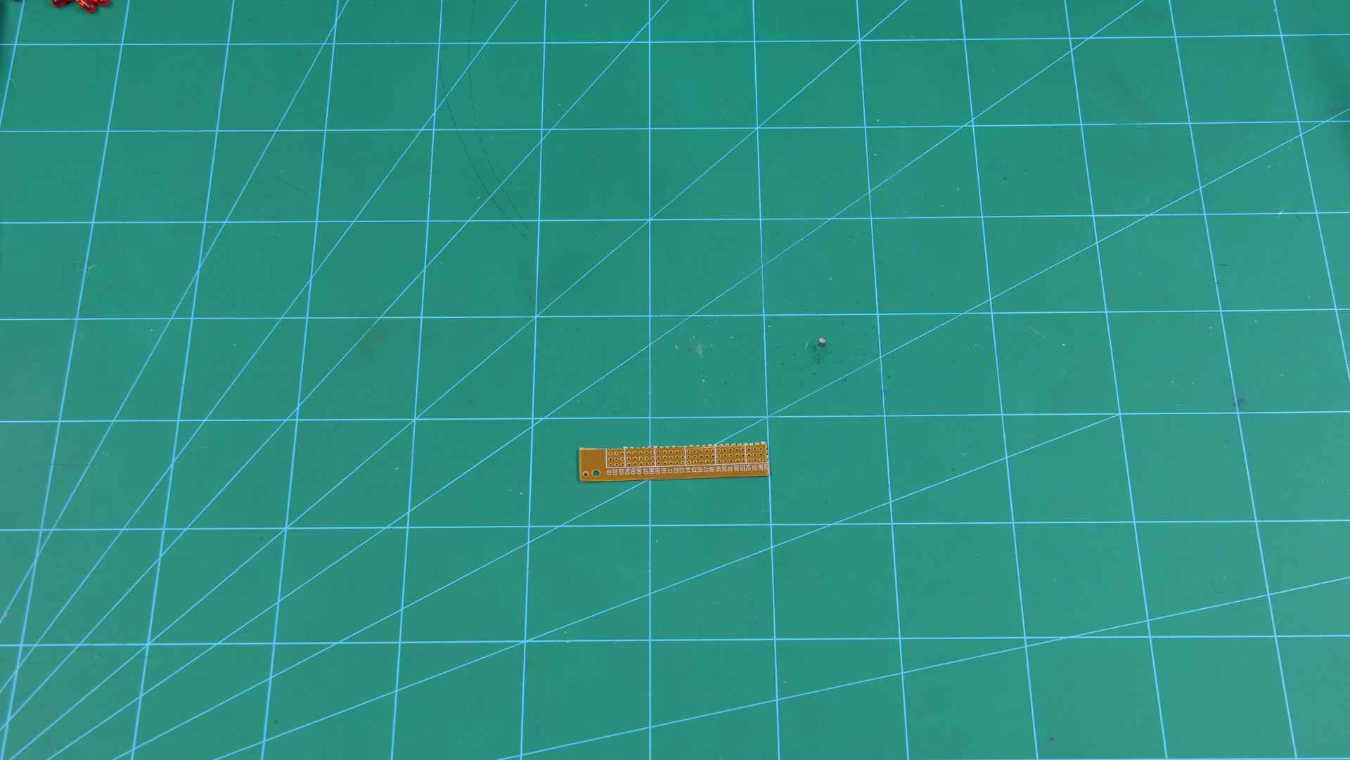
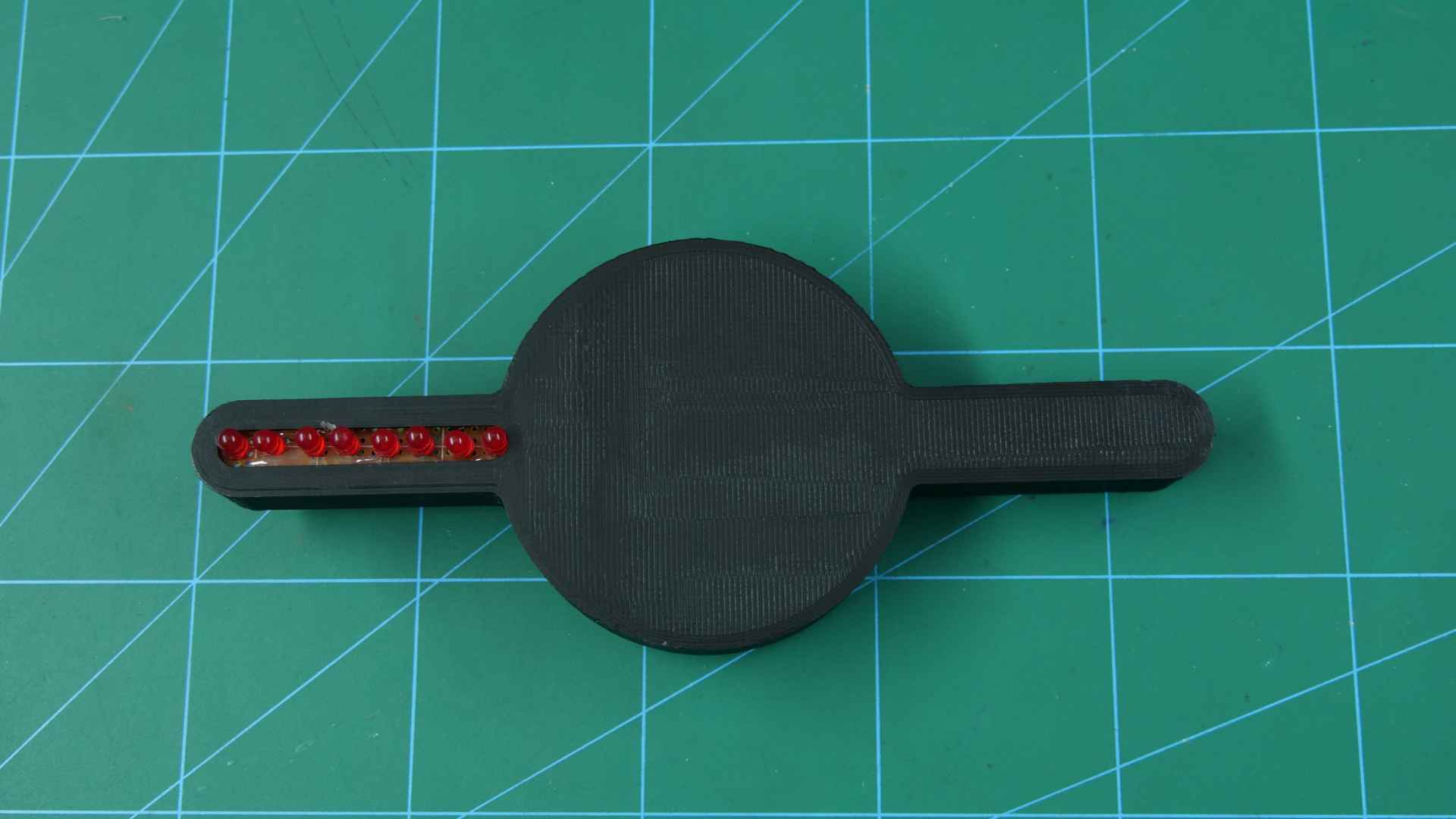
- Cut the General Purpose board (GPB) so that it fits in the 3D Printed Case.
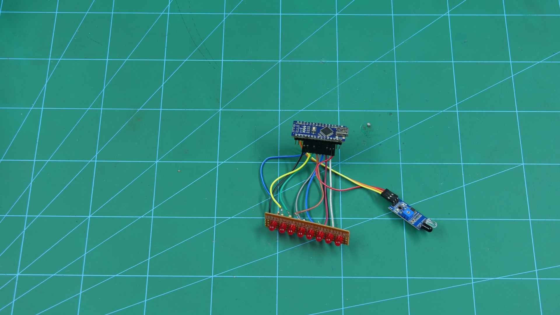
- Once done, fix the LEDs to it. We are going to use 8 red LEDs.
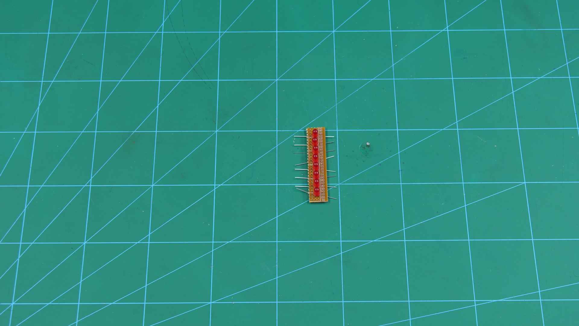
- Now, short (common) the cathode terminal or negative leg of all the LEDs by soldering them on the GPB.
- To protect the LEDs from blowing up due to high voltage supply (5V) we are going to use resistors. We are using 220ohm resistors. Solder one end of each resistor to the anode terminal or positive leg of each LED.
- Solder jumper cables to the second leg of each resistor.
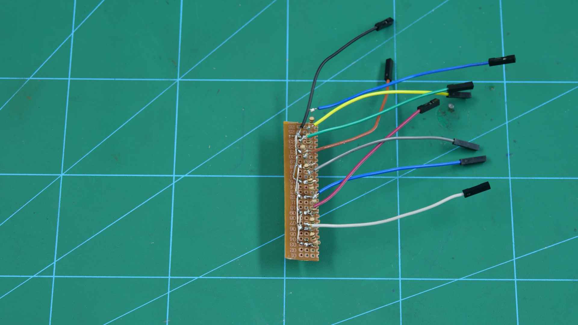
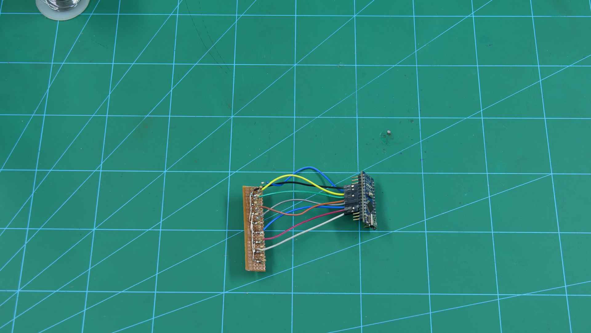
- Connect the free ends to Arduino Nano.
- Now, connect the IR sensor to Nano.
- To power up the Arduino Nano board, connect it to a battery.
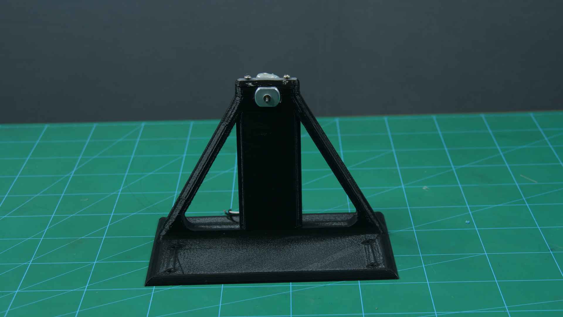
- Now place the complete assembly in the 3D Printed Case.
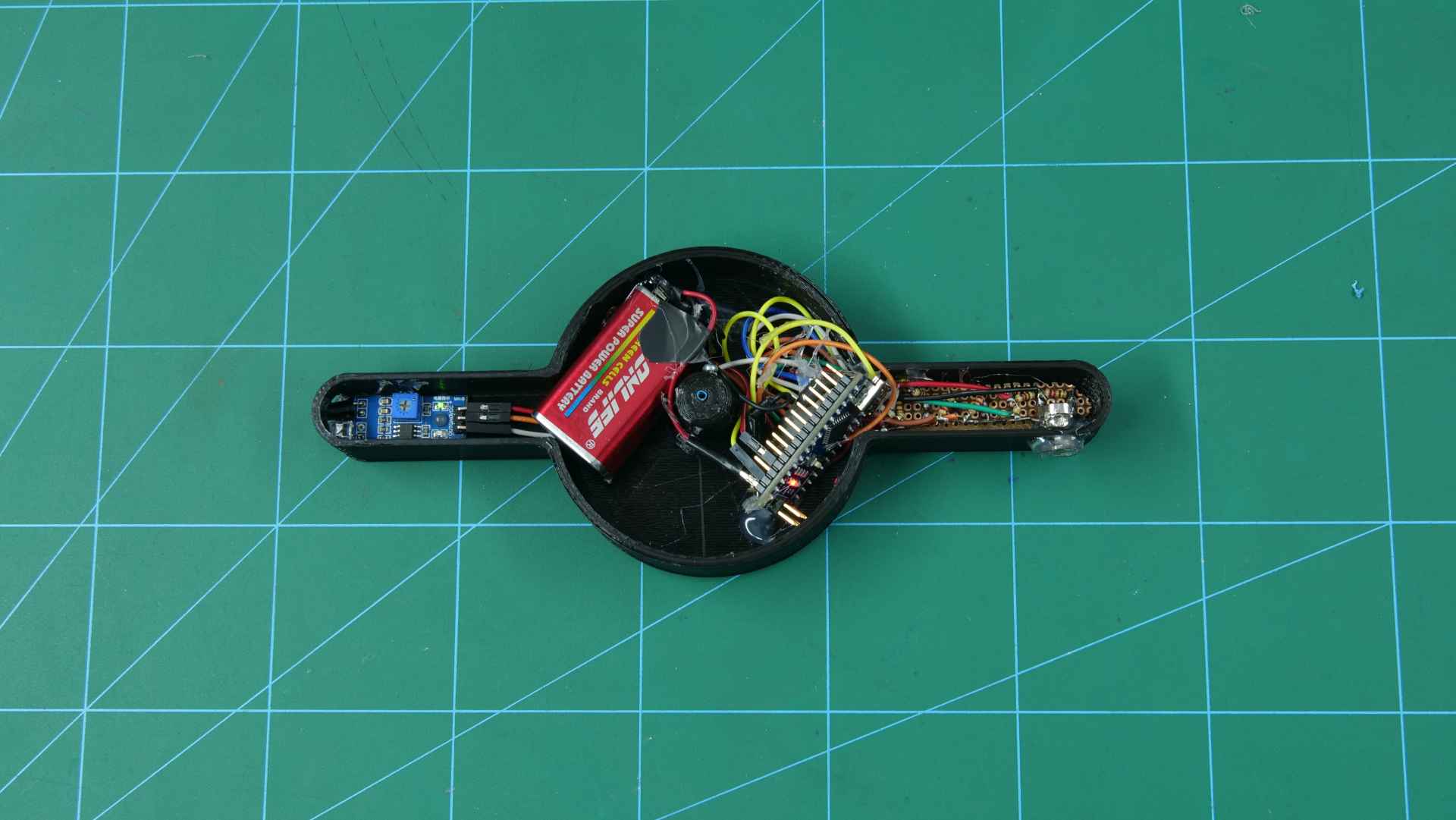
- Fix the DC Motor in the space given in the case. To rotate the motor we need to give it 12V supply. For that, we are using evive. You can also use a 12V battery.
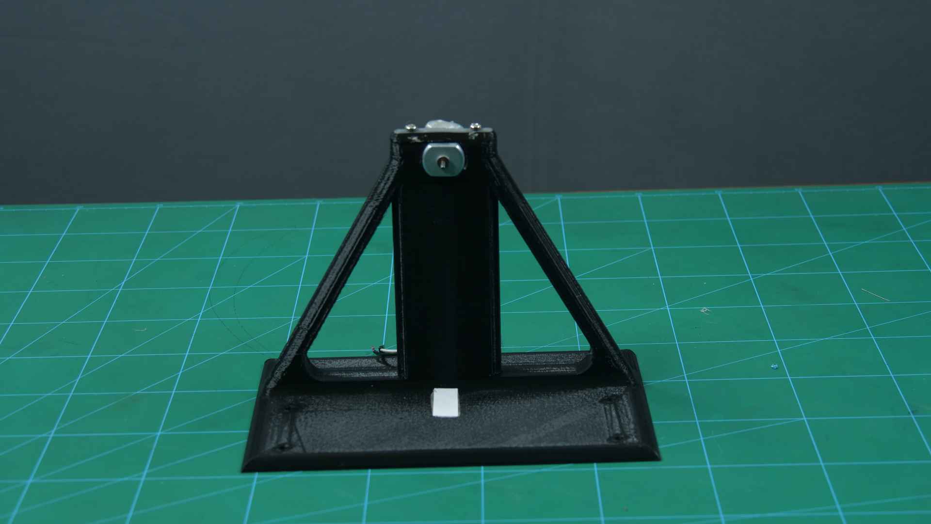
- Attach a white piece of paper on the base of the assembly indicating the point from where the text of image should be displayed. the IR Sensor will be used to detect this piece. Varying the placement of the paper leads to a change in the position of the text displayed.
- Now, fix the rotating part to the Holder.
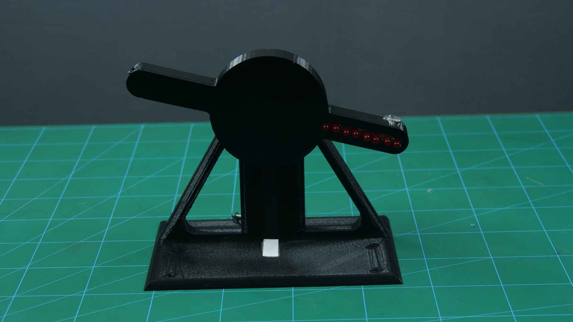
The assembly is now complete.
Connections
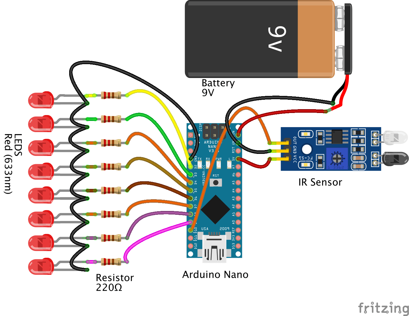
Make the connection as shown:
LED:
- LED0: D2 of nano
- LEd1: D3 of nano
- LED2: D4 of nano
- LED3: D5 of nano
- LED4: D6 of nano
- LED5: D7 of nano
- LED6: D8 of nano
- LED7: D9 of nano
- Common cathode: Ground
IR sensor:
- GND: GND of nano
- Vin: 5v of nano
- Out: D10 of nano
Battery:
- Positive: Vin of nano
- Negative: GND of nano
DC Motor: evive M1 channel
Logic
When the IR sensor detects the white paper, the LEDs start glowing and create the illusion that something is displayed by the LED. This is due to persistence of vision, where the LEDs turn on and off in such a way that the different images overlap each other forming letters.
Arduino Code
Upload the given Arduino code to evive:
Conclusion
With this, your LED POV Display is ready. Have fun!
Only a week left, people! If you haven’t checked out the cool stuff we have for budding and veteran DIYers like you, go have a look at them NOW!


