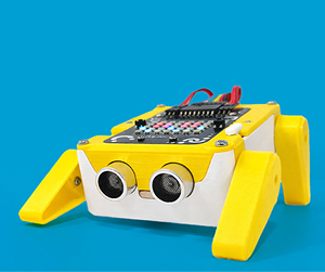
The Quarky Robo Dog Mini is more than just a robot. It is a compact, four-legged walking companion powered by Quarky, an ESP32-based robotics controller designed for hands-on STEM learning. Unlike wheeled robots, the Mini Robo Dog moves on servo-driven legs, making it an excellent platform for studying robot locomotion, joint control, balance, and calibration.
Robo Dog Mini can be programmed using PictoBlox, making it suitable for students, educators, makerspaces, and beginners in robotics who want to explore walking robots in a structured, approachable way.
Download and 3D print all the required parts before starting the assembly if you do not already have them. Also, download the Quarky Robo Dog Mini example file so you can test and program the robot after assembly.
3D Printing files:
Block Coding Files:
Note:
- Follow the assembly steps in sequence to avoid misalignment.
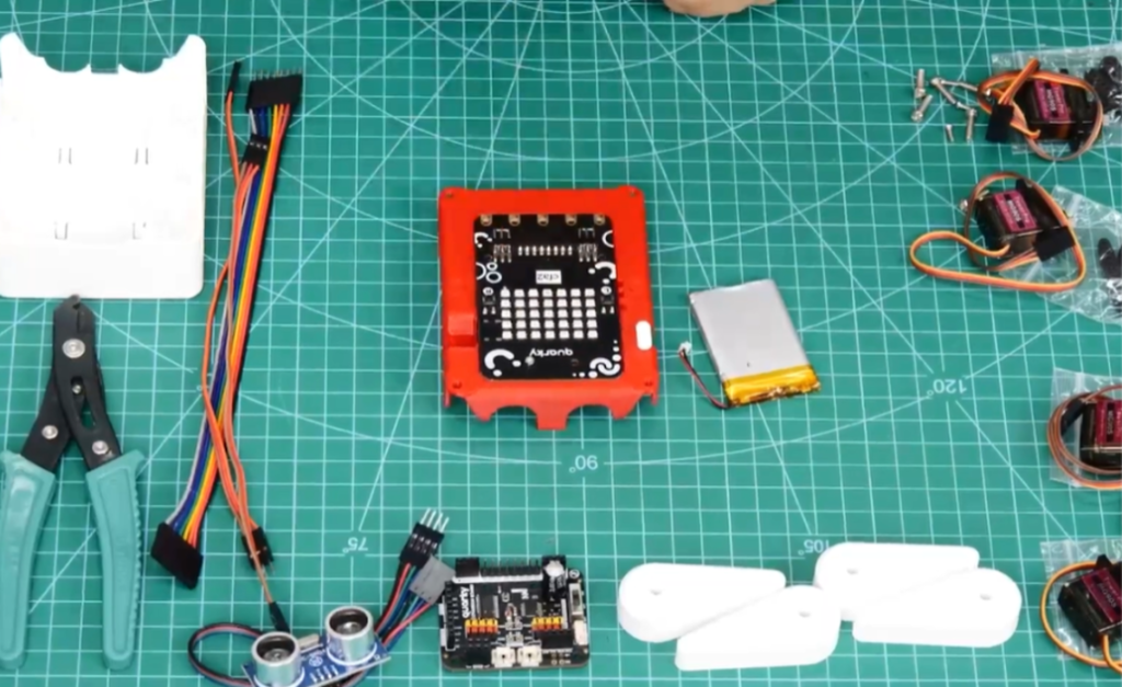
Quarky Robo Dog Mini Components
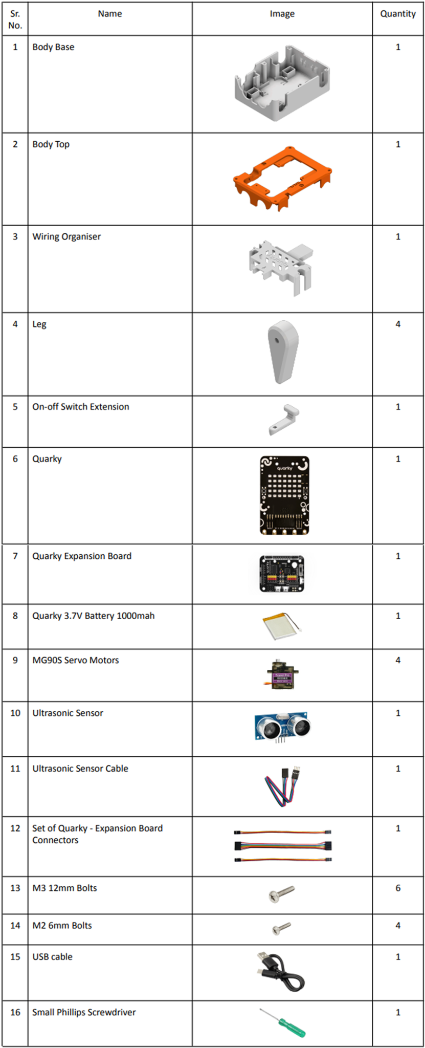
You will also require the following additional tools:
- Side cutter, scissors, or nail cutter (for trimming servo horn)
- Filer (To sand 3D printer parts if required)
Assembly Steps of Quarky Robo Dog Mini
Servo Motor Initialization
Before any physical assembly, all servo motors must be calibrated to 90° to ensure correct alignment.
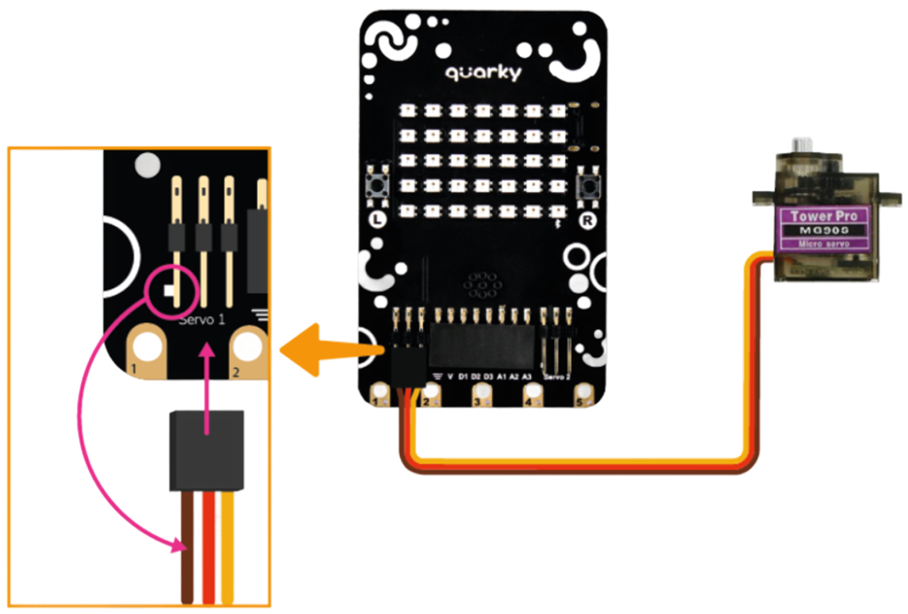
Step 1: Connect the First Servo to Quarky
Take one MG90S Servo Motor and connect it to the first Servo Connector port on the Quarky board.
When plugging in the servo connector, make sure the brown wire is on the left side. This is the ground wire, and plugging it in the wrong direction can damage the servo or the board.
Step 2: Make sure PictoBlox is installed on your device.
PictoBlox is the software you will use to send commands to Quarky and calibrate the servo motors.
If PictoBlox is not already installed on your computer, visit the PictoBlox Download Page, choose your operating system, and install the latest version.
Note: Please use PictoBlox version 9.1.0 or later to support Quarky’s latest Extensions.

Step 3: Open PictoBlox and select the Block Coding environment.
Once PictoBlox is installed and open, you will see different environment options on the home screen.
Click on Block Coding to enter the visual block-based programming environment. This is where you will write the calibration script.

Step 4: Connect your Quarky to your computer using a USB cable.
Use a USB cable to connect your Quarky board to your computer. Make sure the cable is firmly plugged in on both ends into Quarky and into your computer’s USB port.
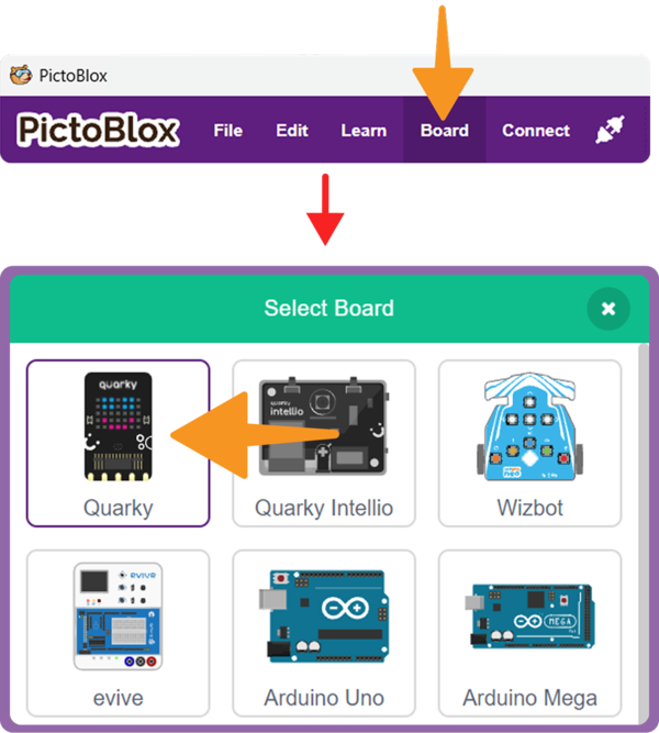
Step 5: Click on the Board button from the toolbar and select Quarky.
In PictoBlox, look at the toolbar at the top of the screen and click on the Board button. From the dropdown menu that appears, select Quarky. This tells PictoBlox which hardware you are using.
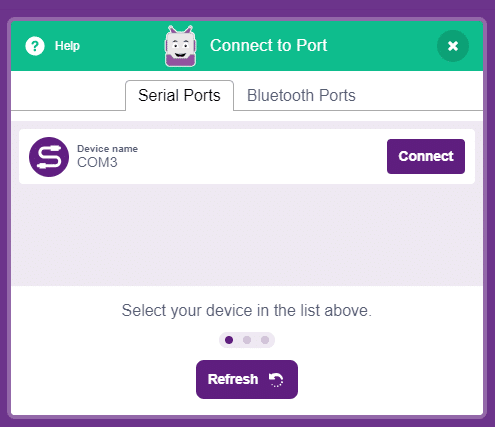
Step 6: Select the appropriate Serial Port Connection method if connected via USB, or the Bluetooth Port if connecting wirelessly, then press Connect.
Step 7: Run the servo Initialization Script
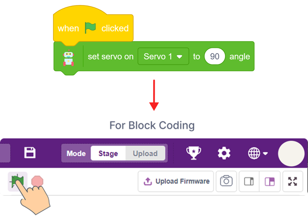
Now you will write a small program in PictoBlox to set the servo to 90°.
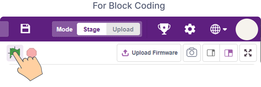
In the Block Coding environment, create the servo initialization script as shown in the guide’s reference image. Once it is ready, click the Green Flag button to run it.
- If the servo motor makes a small spinning sound, it has just moved to 90°. That is correct.
- If there is no sound at all, the servo was already at 90°. That is also fine.
 Step 8: Repeat for All Servos
Carefully unplug the first servo motor from Quarky and repeat Steps 1 through 7 for each of the remaining three servo motors.
All four MG90S Servo Motors must be individually calibrated to 90° before assembly. Do not attach any legs until this phase is fully complete.
You can refer to Servo Motors & Calibration – Quarky for more info.
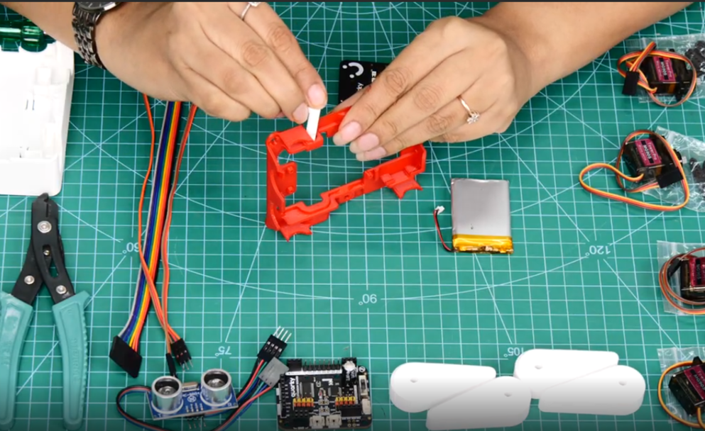
Assembling the Body Top
Step 9: Insert On-Off Switch Extension
Take the On-Off Switch Extension (a small 3D printed piece) and press it firmly into its designated slot on the Body Top.
This piece acts as an extended arm for Quarky’s built-in power switch, so you can turn the robot on and off without opening the body.
Step 10: Place Quarky on the Body Top
Set the Quarky board down onto the Body Top, with the power switch on Quarky aligned directly over the On-Off Switch Extension you just inserted.
The correct alignment is important; if the switch is off-centre, you will not be able to turn the robot on and off properly after the body is closed.
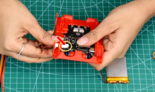
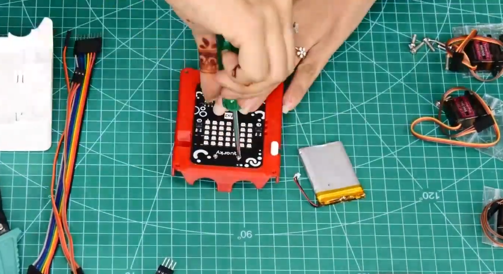
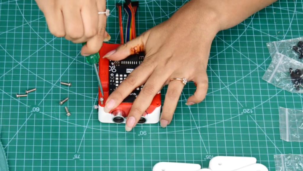
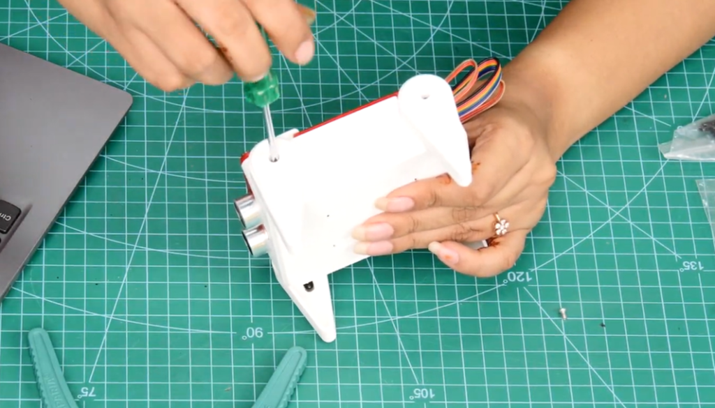
Step 11: Secure Quarky With M2 Bolts
Secure Quarky onto the Body Top using M2 6mm Bolts, ensuring Quarky’s power switch remains correctly aligned with the On-Off Switch Extension.
Note: Keep Quarky powered ON and the switch extension fully inserted into the Body Top to help with alignment. After securing the board, switch Quarky OFF before proceeding for safety.
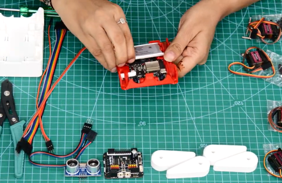
Step 12: Connect and Place Battery
Take the 3.7V Li-ion Battery (1000 mAh) and connect its cable to the battery port on the Quarky board.
Once connected, place the battery into the battery slot on the Body Top, pressing it in gently until it sits securely in the designated space.
Preparing the Body Base
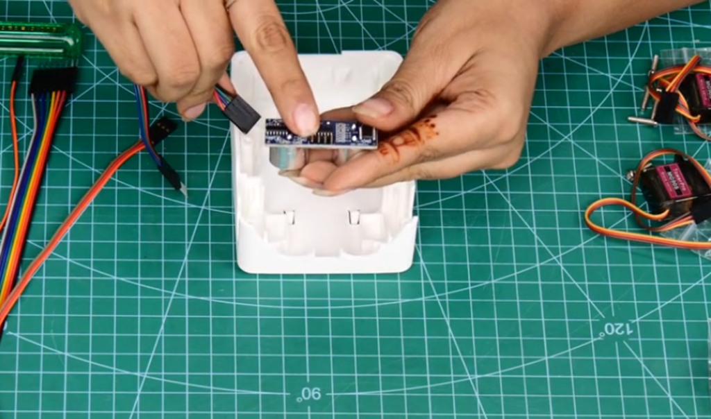
Step 13: Attach Ultrasonic Sensor Cable
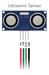
Take the Ultrasonic Sensor Cable and plug it into the Ultrasonic Sensor.
Make sure the connector is firmly seated. A loose cable here will cause the sensor to stop working during operation.
For more information about how the ultrasonic sensor works, refer to the guide: Introduction to Ultrasonic Sensors and Quarky.
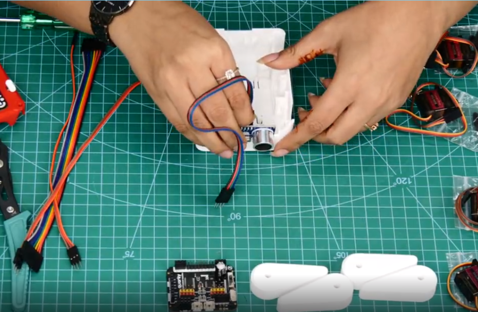
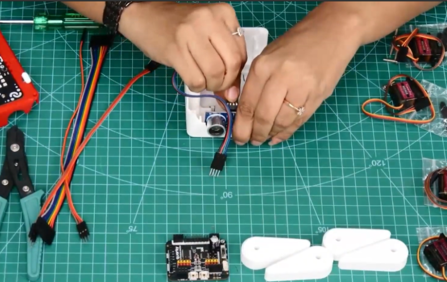
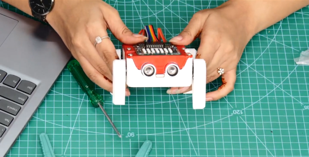
Step 14: Insert Ultrasonic Sensor
Take the Ultrasonic Sensor (with its cable now attached) and slide it into its designated slot at the front of the Body Base.
Make sure the sensor’s two circular eyes are facing forward, pointing out from the front of the robot. This is the direction the robot will use to detect objects in its path.
Step 15: Place the Expansion Board on the Body Base
Take the Quarky Expansion Board and place it onto the Body Base in its designated mounting position.
Press it down until it snaps firmly into place.
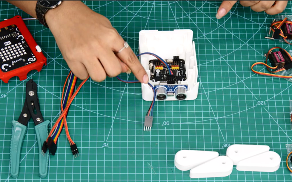
Step 16: Bend Ultrasonic Sensor Pins
Look at the pins on the Ultrasonic Sensor. The sensor’s pins are straight by default. However, depending on the version of the sensor and how it fits in the Body Base, you may need to carefully bend or adjust the 2.54mm Male Header Pins so they reach the Expansion Board ports properly.
Do this gently using your fingers or a small tool. Avoid applying too much force, as the pins can break if bent too aggressively.
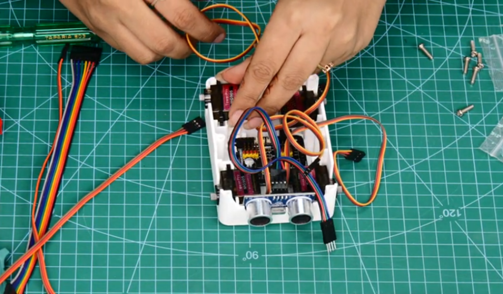
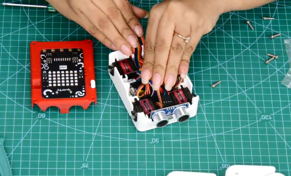
Step 17: Insert All Four Servo Motors
Take all four MG90S Servo Motors and insert each one into its matching slot on the Body Base.
There are four dedicated motor slots, one for each leg position (front-left, front-right, rear-left, rear-right).
Connecting Electronics and Finalizing the Body
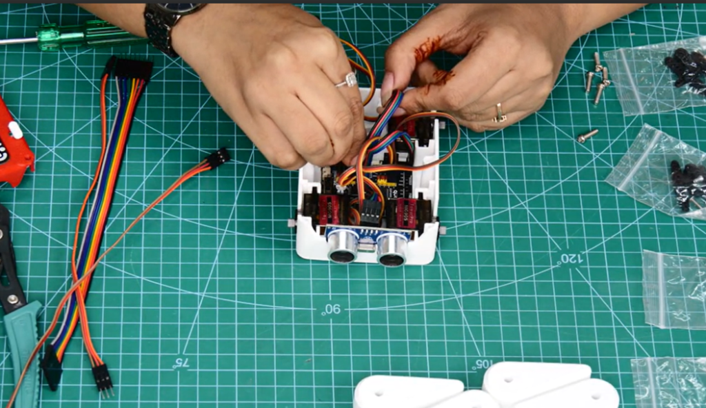
Step 18: Connect Servo and Sensor Cables
Connect the cable from each of the four MG90S Servo Motors and the Ultrasonic Sensor Cable to their correct ports on the Quarky Expansion Board.
Each port on the Expansion Board is labelled or has a specific position. Match each cable to the correct port carefully.
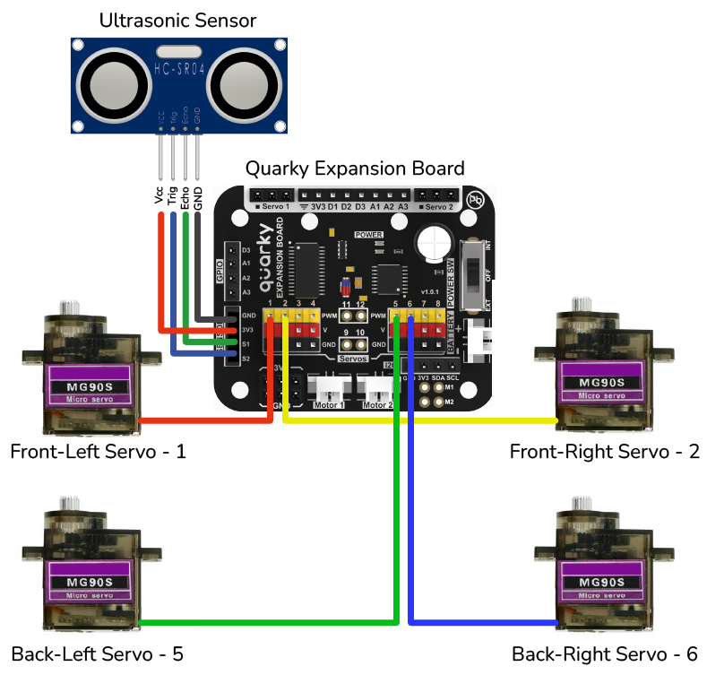
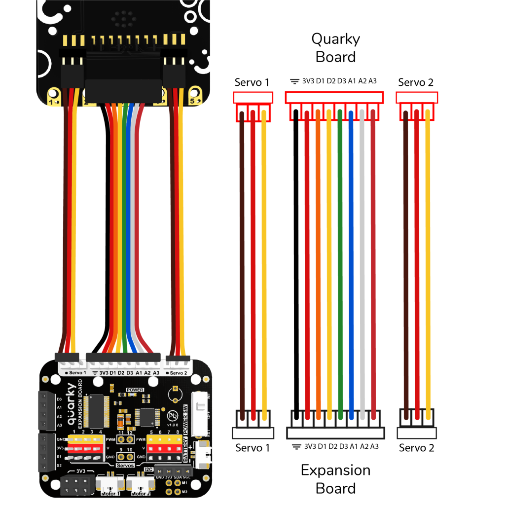
Step 19: Connect Expansion Board Connectors
Take the Set of Quarky Expansion Board Connectors and connect one end to the Quarky Expansion Board on the Body Base.
Follow the wiring diagram provided in the reference guide carefully to ensure the connector is attached to the right side and in the right orientation.
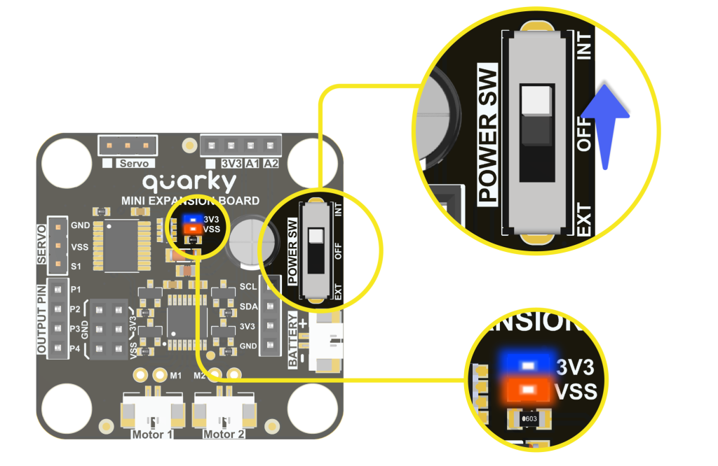
Note: Please set the Quarky Expansion Board to Internal Mode before proceeding.
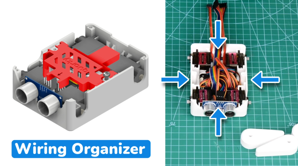
Step 20: Organise Cables With Wiring Organiser
Before closing the body, take all the cables inside the Body Base and arrange them neatly so they are not tangled, pinched, or sticking out.
Once the cables are organised, press the Wiring Organiser (3D printed piece) over them to hold everything in place.
Step 21: Join Body Top and Base With M3 Bolts
Place the Body Top-down onto the Body Base, aligning all edges and internal components.
Before pressing them fully together, do a quick check:
- Are all cables inside and not caught between the two halves?
- Is the Expansion Board connector cable visible and accessible at the top?
Once aligned, secure both halves together using the M3 12mm Bolts. Tighten them evenly all around.
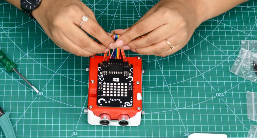
Step 22: Connect Connectors to Quarky
Take the other end of the Set of Quarky Expansion Board Connectors and connect it to the Quarky board on the Body Top.
Refer to the same wiring diagram from Step 19 to make sure the connector is attached correctly on this end, too.
Step 23: Bend Connectors to Form Tail
Once both ends of the Expansion Board Connector are plugged in, gently bend the excess ribbon cable outward at the back of the robot.
Leave approximately 3 to 4 centimetres of the connector sticking out. This forms the Robo Dog Mini’s small decorative tail.
Attaching the Legs
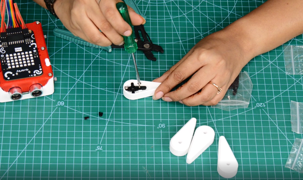
Step 24: Trim Servo Double Arms
Make sure all servo motors are confirmed at 90° (neutral position) before attaching any legs.
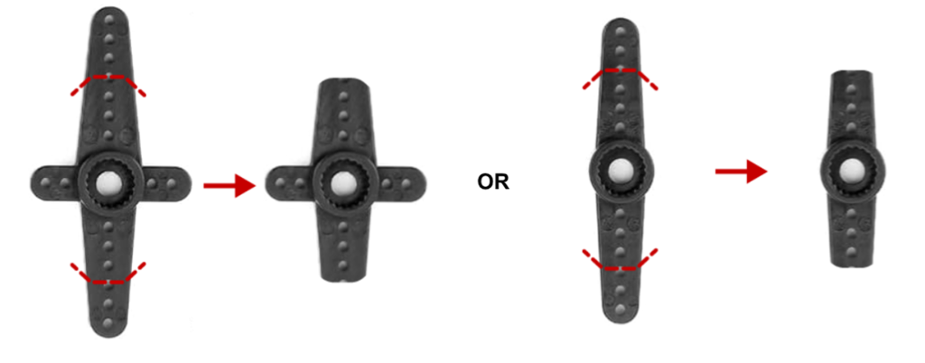
Each servo motor comes with a Servo Double Arm, a small cross-shaped plastic horn piece. These arms need to be trimmed slightly so they slide cleanly into the leg slots.
Using your side cutter, scissors, or nail cutter, trim the Servo Double Arms as shown in the diagram below.
Note: Make sure three holes remain on the Servo Double Arms after trimming.
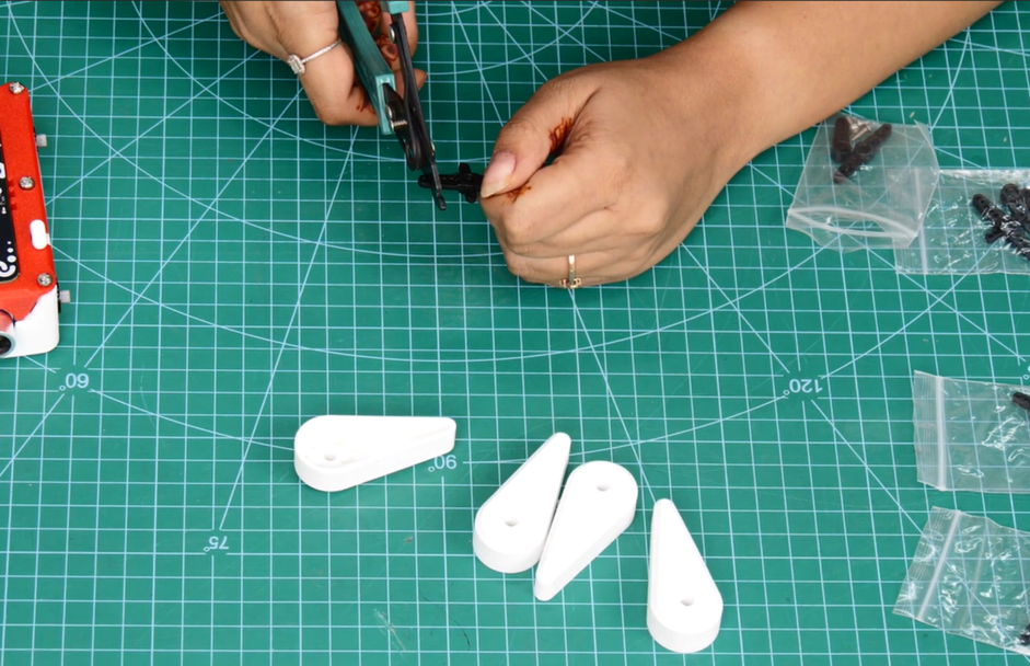
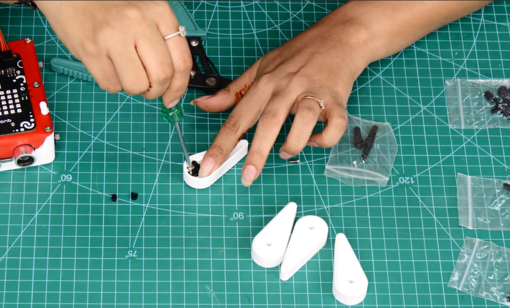
Step 25: Affix Servo Arms to Legs
Take a trimmed Servo Double Arm and align it inside the mounting slot on one of the 3D printed Legs.
Secure the arm to the leg using the M2 Screws included in the servo motor accessories pouch.
Repeat this for all four legs.
Note: Different types of Servo Double Arms may require different attachment orientations inside the Legs.
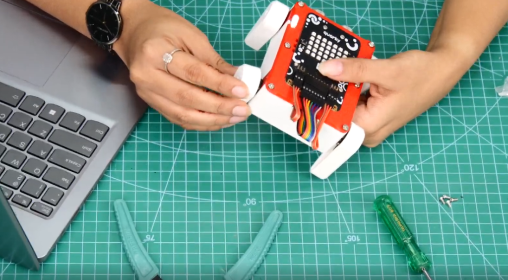
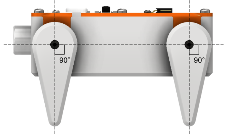
Step 26: Attach Legs to Servo Shafts
Attach the assembled Legs onto the servo motor shafts. Mounting orientation is critical. When the leg is attached, it should be standing straight up and down perpendicular to the robot’s body. Think of it as the robot standing in a normal upright position.
Repeat for all four legs.
Step 27: Secure Legs With M2 Bolts
Once all four legs are positioned correctly on their servo shafts, secure each one firmly using the M2 Bolts from the servo motor accessories pouch.
Tighten each bolt carefully. The bolts go through the centre hole of the Servo Double Arm and thread into the servo shaft to lock the leg in place.
Step 28: Assembly Complete
Your Quarky Robo Dog Mini is now fully assembled.
Before powering on, do a final check:
- All four legs are standing straight and vertical
- All M2 and M3 bolts are tightened
- No cables are sticking out from the sides or caught between moving parts
- The battery is connected and seated properly
- The wiring inside is organized and secured with the Wiring Organizer
Programming With PictoBlox
Step 29: Open Project and Connect Quarky
- Ensure the latest version of PictoBlox is installed for smooth operation. You can check for the latest version or Download PictoBlox.
- Open the Quarky Robo Dog Mini.sb3 project file in PictoBlox.
- Connect your Quarky using either the Serial Port Connection method or the Bluetooth connection method.
Step 26: Click Green Flag to Run Program
Click the Green Flag to execute the program.
Step 30: Operate Using Keyboard Keys
Use the following keyboard keys to operate the Robo Dog Mini:
X — Calibrate servos
0 — Legs down (sit)
1 — Say Hi
2 — Dance
3 — Splot (fun action)
5 — Stand straight
6 — Pee
7 — Go forward
8 — Legs stand
You can now explore walking patterns, balance control, and interactive behaviours, or create your own steps and functions using PictoBlox. Have fun with your new companion!
Now that your Quarky Robo Dog Mini is assembled and ready to go, you can take your robotics journey even further. Quarky is a versatile robotics controller that powers a wide range of exciting AI, robotics, and automation projects.
If you enjoyed building and programming the Robo Dog Mini, explore these additional Quarky-based projects to expand your skills in robotics, coding, and artificial intelligence:
- Robot Pet with Python – Build an intelligent robotic pet that can interact, respond, and perform engaging actions using Python programming.
- AI Delivery Robot with Python – Create a smart delivery robot capable of navigating and transporting objects autonomously.
- Wirelessly Controlled Robot with Python– Learn how to control a robot remotely using wireless communication and Python.
These projects are perfect for students, educators, makerspaces, and robotics enthusiasts who want to continue experimenting with Quarky.