We are going to follow the steps in this lesson to assemble the Quarky Humanoid Robot.
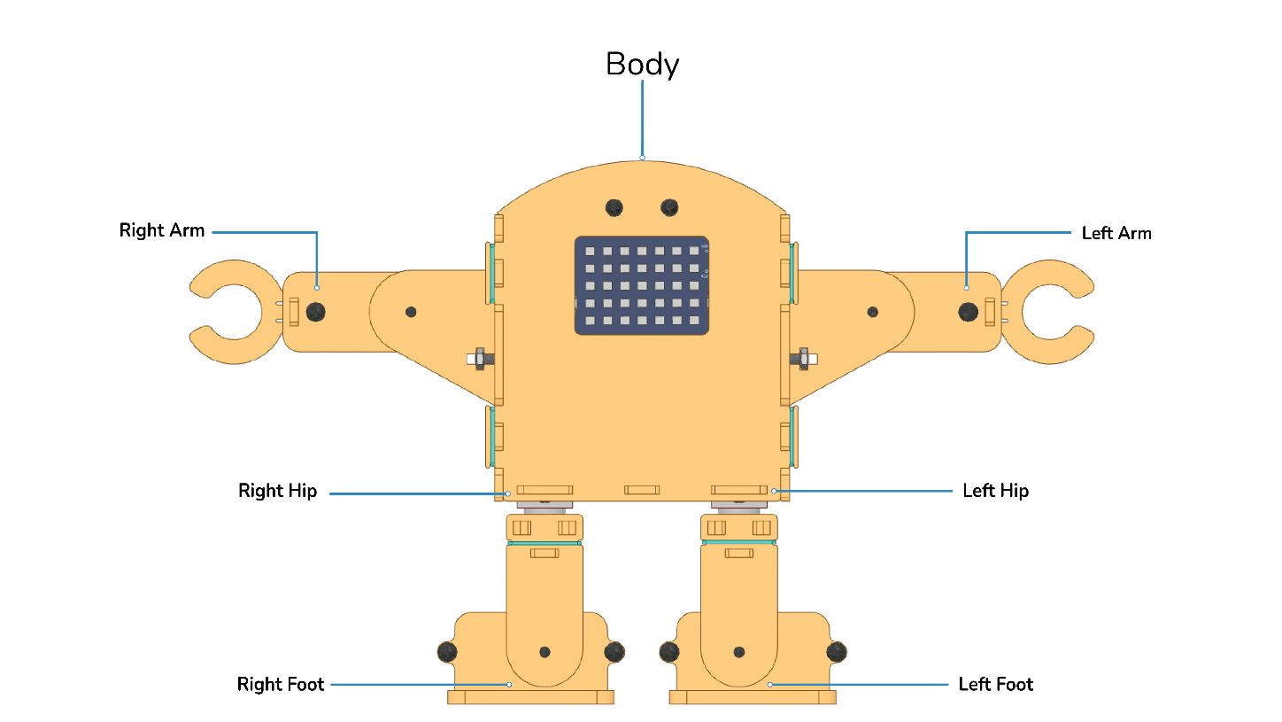
Before we begin, take a look at the picture of the Humanoid robot to get a better understanding of the different parts of the robot. The centre part of the robot is referred to as the Body. There are 2 hands controlled by 2 servo motors, 2 hip joints to move the leg, and 2 leg joints to move the foot of the robot.
Servo Initialization
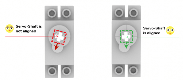
Firstly we need to calibrate the servo motors, i.e., we need to first set all eight of them to 90 degrees. This will ensure that the angle of each servo motor is properly aligned. Follow the steps:
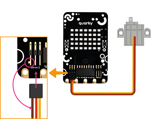
- Connect the first servo motor to the first Quarky Servo Connector, ensuring that the brown wire is on the left side.
- Connect Quarky to your laptop using a USB cable.
- Open PictoBlox on your desktop. After that, select Block Coding as your coding environment.

- Then, click the Board button in the toolbar and select board as Quarky.

- Next, select the appropriate Serial port if the Quarky is connected via USB or the Bluetooth Port if you want to connect Quarky via Bluetooth and press Connect.

- Quarky is now connected to PictoBlox. Create the following script:

- Click on the green flag over the stage to run the script. You will find that the servo motor shaft gets perfectly aligned.
- Remove the servo motor from Quarky and repeat the process for all 6 servos.
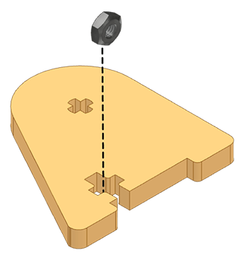
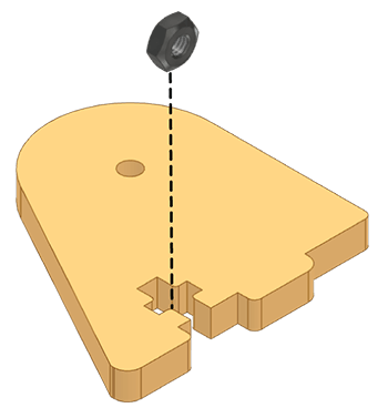
- Insert an M3 Nut in the horizontal slot on both the Shoulder-Back and Shoulder-Front.
Arms Assembly
Follow the steps:
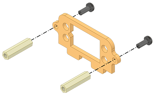
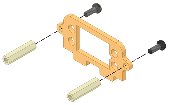
- Fix the M3 Spacers (20mm) to the Arm-Back using M3 Bolts (8mm).
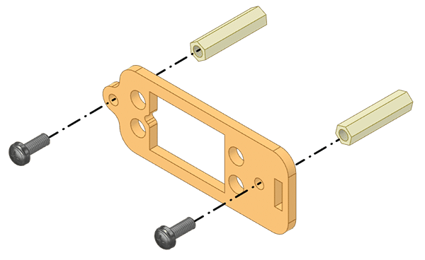
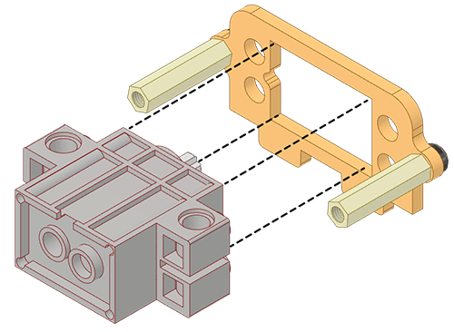
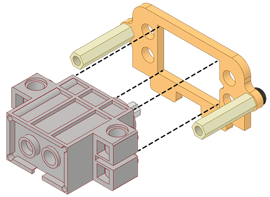
- Insert the 180° Servo Motor in the Arm-Back.
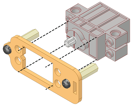
 Alert: Keep the Servo Motor’s shaft towards the notch in the servo profile.
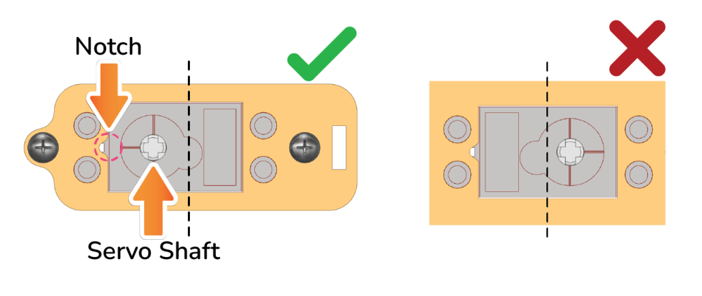
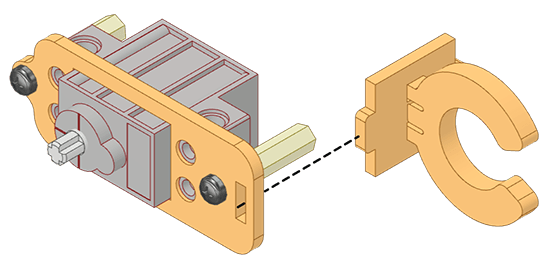
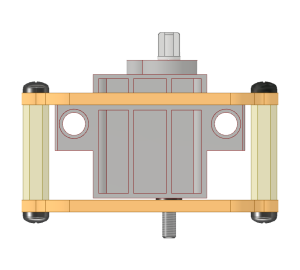
- Carefully snap the Hand-End into the Arm-End.
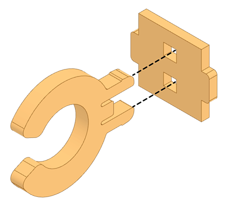
- Insert the Arm-End into the slot in Arm-Back.
- Now insert an M3 Bolt (12mm) through the Arm-Front and fix it on the Arm-End. Fix Arm-Front on the M3 Spacers (20mm) with M3 Bolts (8mm).
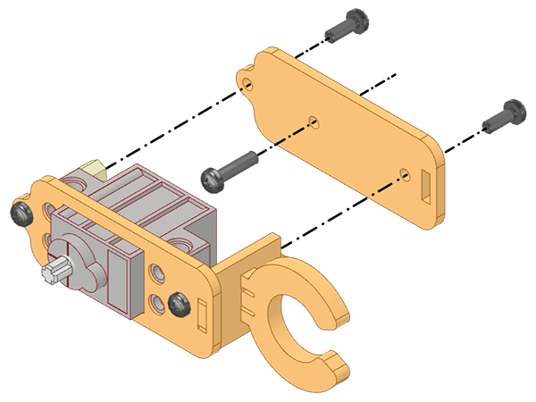
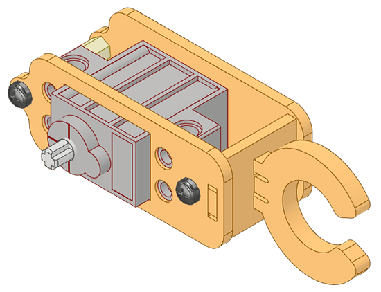
- Now repeat steps 1 to 5 for the other arm.
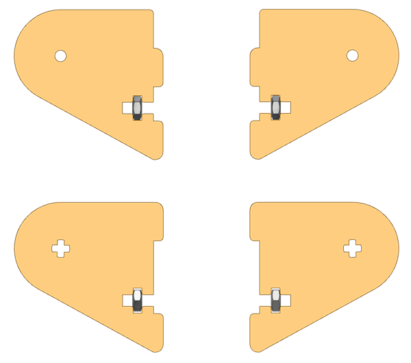
Left Shoulder Assembly
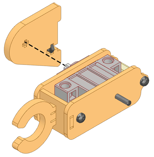
- Attach a Shoulder-Back to an arm’s 180° Servo Motor shaft.
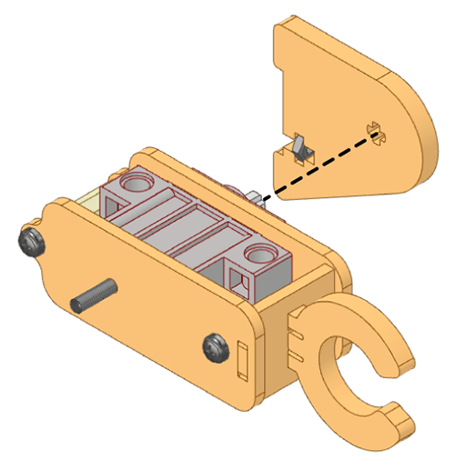 Alert: Ensure the orientation of the parts is as per reference.
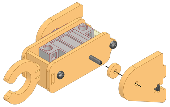
 - Pass a Ring-Spacer and a Shoulder-Front through the M3 Bolt (12mm) on the front side of the Arm.
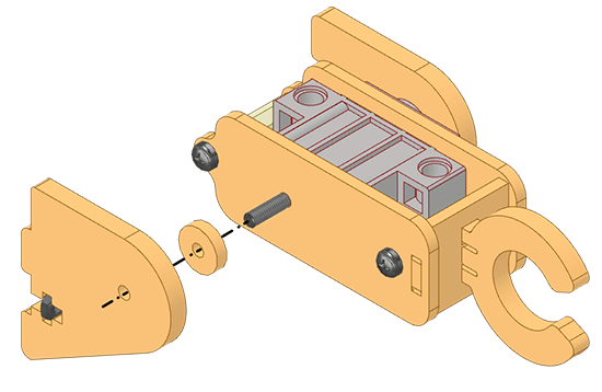
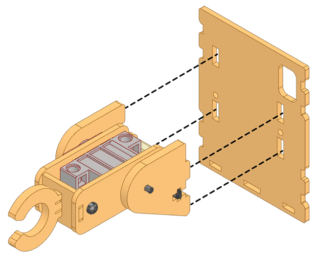
- Now, fix both the Shoulder-Front and Shoulder-Back simultaneously to Body-Side from its left side.
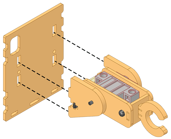
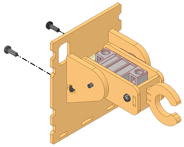
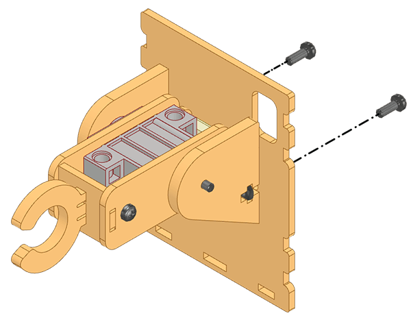
- Finally, secure them firmly with M3 Bolts (8mm).
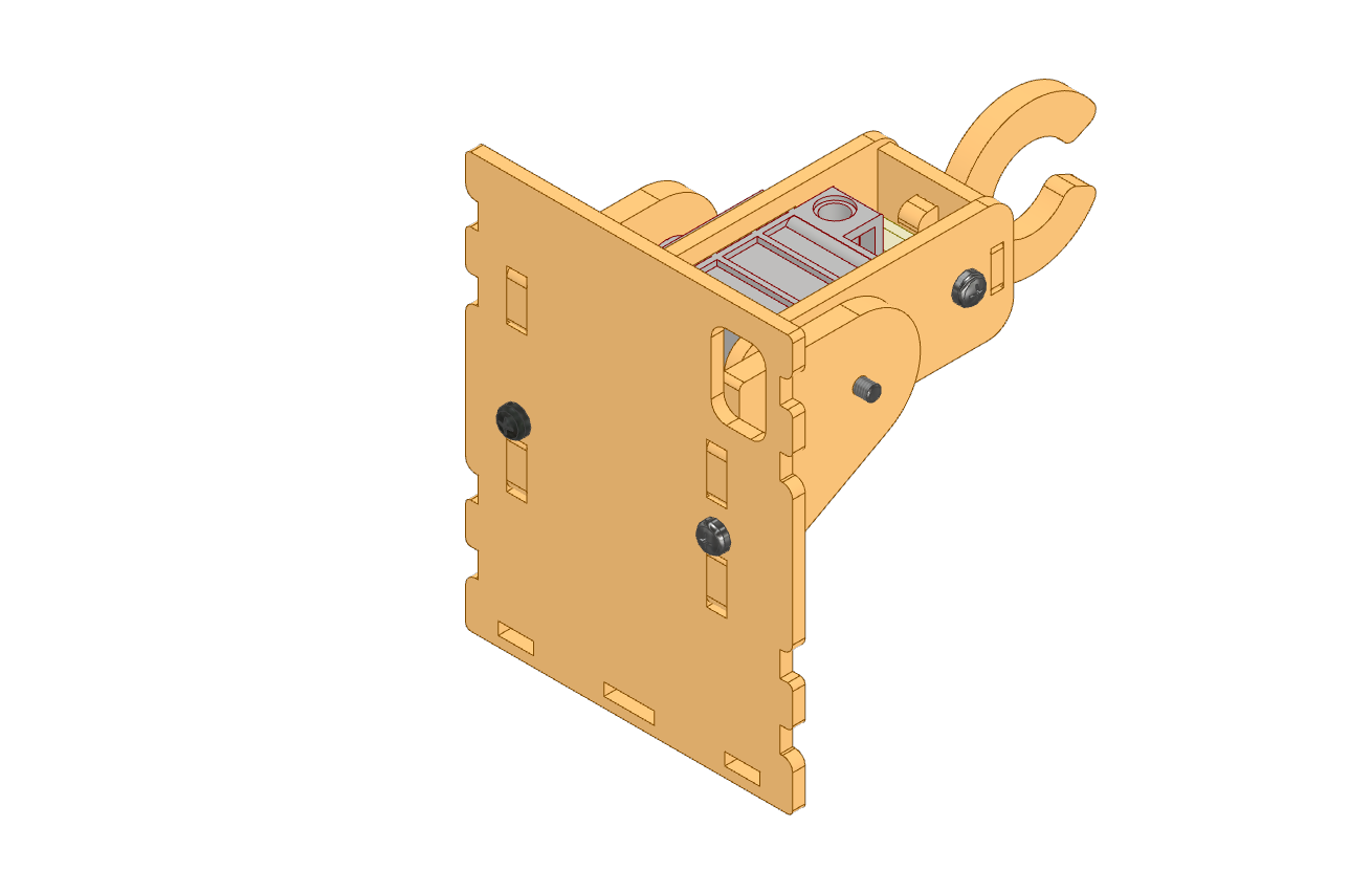
Assembled:
Right Shoulder Assembly
- Attach a Shoulder-Back to an arm’s 180° Servo Motor shaft.
 Alert: Ensure the orientation of the parts is as per reference.
 - Pass a Ring-Spacer and a Shoulder-Front through the M3 Bolt (12mm) on the front side of the Arm.
- Now, fix both the Shoulder-Front and Shoulder-Back simultaneously to Body-Side from its right side.
- Finally, secure them firmly with M3 Bolts (8mm).
Assembled:
Left Foot Assembly
- Fix M3 Spacers (20mm) on Foot-Back using M3 Bolts (8mm).
- Insert the 180° Servo Motor in the Foot-Back.
 Alert: Keep the 180° Servo Motor shaft towards the notch in the servo profile.
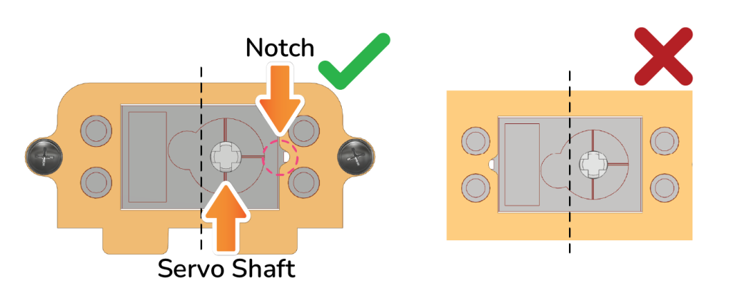
- Secure an M3 Bolt (8mm) between the Foot-Front and the 180° Servo Motor. Fix the Foot-Front using two other M3 Bolts (8mm).
 Top View:
Alert: After assembly, the bolt will be aligned with the 180° Servo Motor shaft on the back of the 180° Servo Motor. - Next, insert this assembly into the Foot-Base.
 Note: If you are finding it difficult because the slot is too loose or too tight to press-fit MDF parts, please try again after flipping the part.
Left Leg Assembly
- Fix Leg-Back to the Left Foot’s 180° Servo Motor’s-shaft, ensuring the Leg’s perpendicularity to the Foot.
- Insert Leg-Top A and Leg-Top B into the slots of Leg-Back.
- Insert Leg-Top A and Leg-Top B into the slots of Leg-Front while passing the Leg-Front through the M3 Bolt (8mm) coming out of the Left-Foot.
- Secure the Upper Left Leg using a Rubber band around the grooves on the edges of the Leg-Front and Leg-Back.

Assembled:
Right Fool Assembly
- Fix M3 Spacers (20mm) on Foot-Back using M3 Bolts (8mm).
- Insert the 180° Servo Motor in the Foot-Back.
 Alert: Keep the 180° Servo Motor shaft towards the notch in the servo profile.
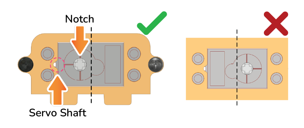
- Secure an M3 Bolt (8mm) between the Foot-Front and the 180° Servo Motor. Fix the Foot-Front using two other M3 Bolts (8mm).

Top View:
 Alert: After assembly, the bolt will be aligned with the 180° Servo Motor shaft on the back of the 180° Servo Motor.
 - Next, insert this assembly into the Foot-Base.
Right Leg Assembly
- Fix Leg-Back to the Right Foot’s 180° Servo Motor’s-shaft, ensuring the Leg’s perpendicularity to the Foot.
- Insert Leg-Top A and Leg-Top B into the slots of Leg-Back.
- Insert Leg-Top A and Leg-Top B into the slots of Leg-Front while passing the Leg-Front through the M3 Bolt (8mm) coming out of the Left-Foot.
- Secure the Upper Left Leg using a Rubber band around the grooves on the edges of the Leg-Front and Leg-Back.
Assembled:
Body Assembly
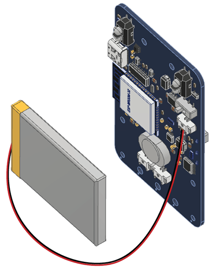
- First, connect the Battery by placing it on the backside of the Quarky. Keep the red wire towards the right side.
- Mount and snap the A1 Purple Parts to keep the Battery safe and secure.
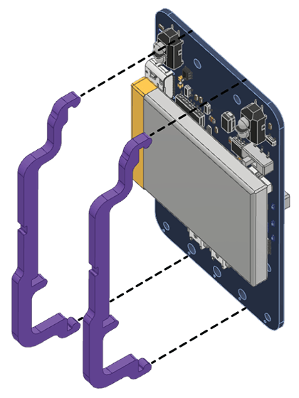
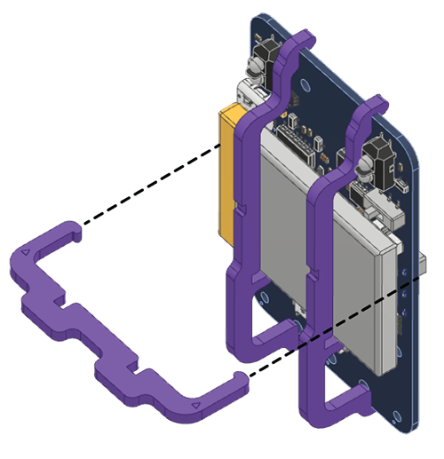
- Next, lock the A1 Purple Parts with the help of an A2 Purple Part. Press the parts gently to snap them.
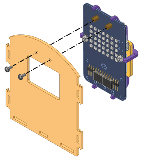
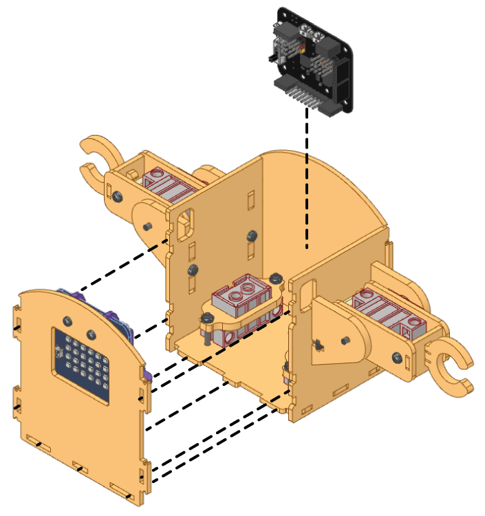
- Fix M2.5 Standoffs (5mm) on Quarky using M2.5 Nuts.
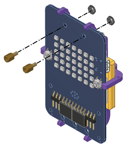
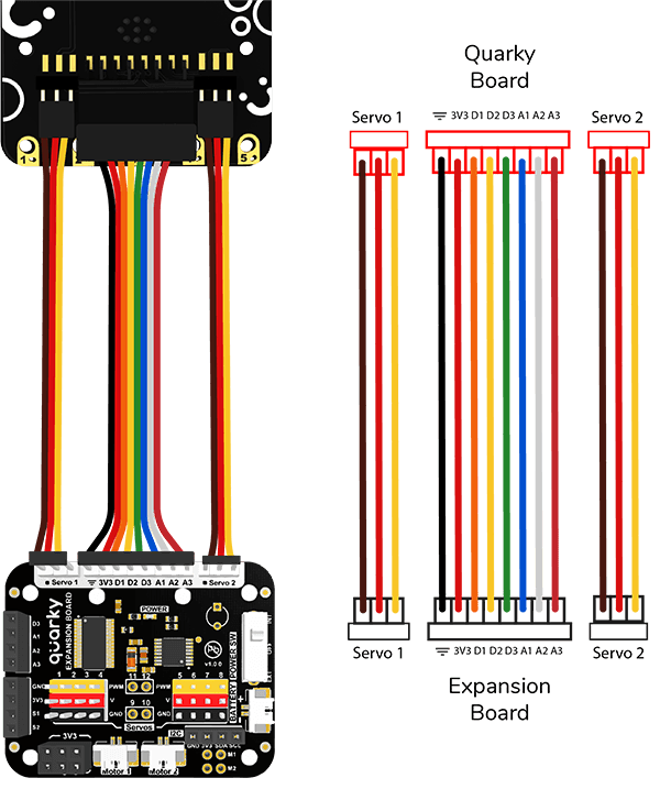
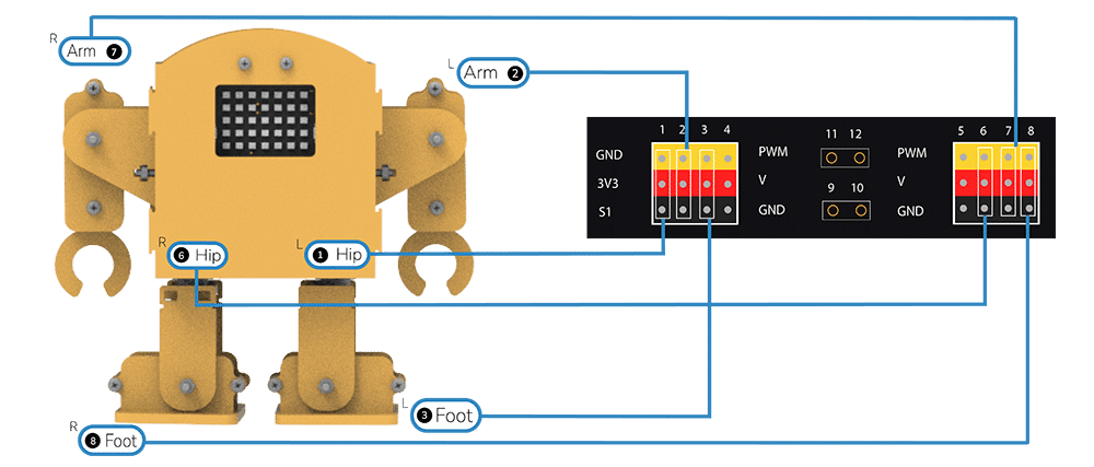
- Connect the Expansion Connectors to the Quarky [refer to the wiring diagram].
- Fix Quarky on the Body-Front using M2.5 Bolts (5mm).
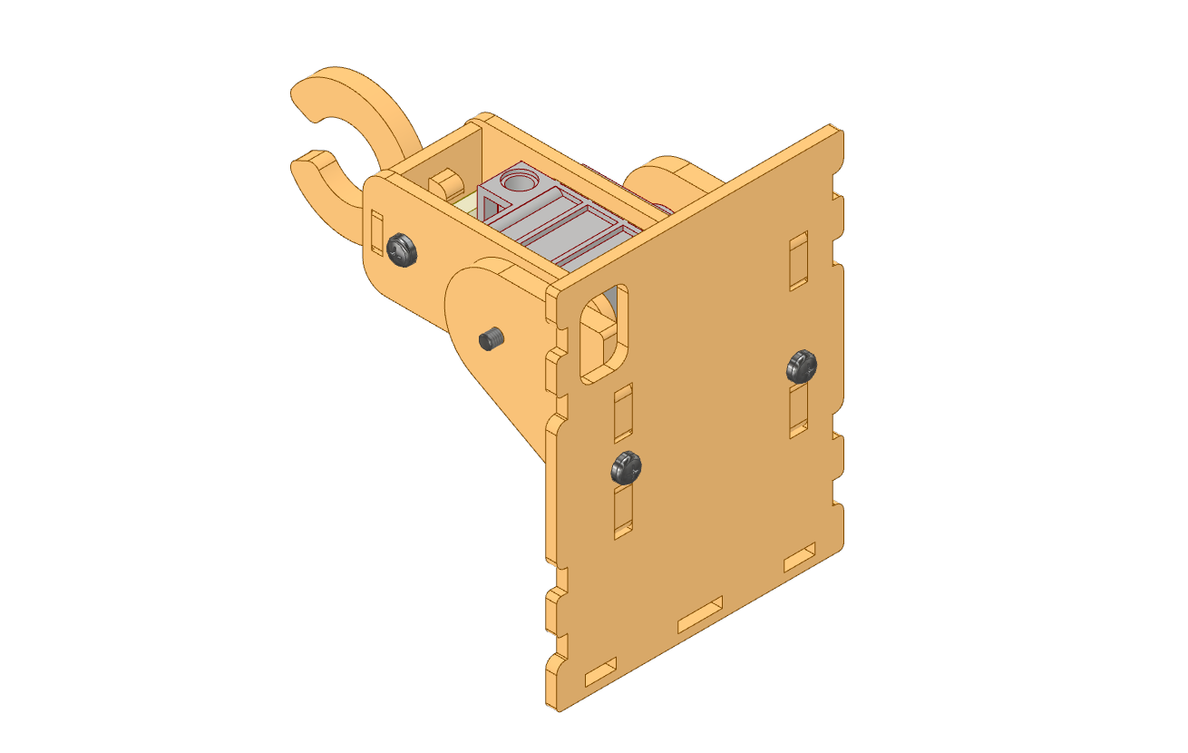
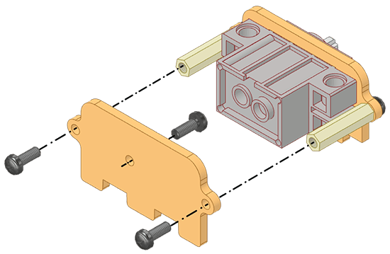
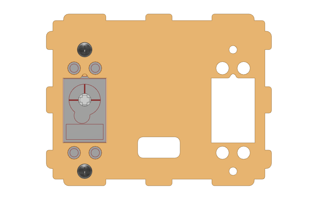
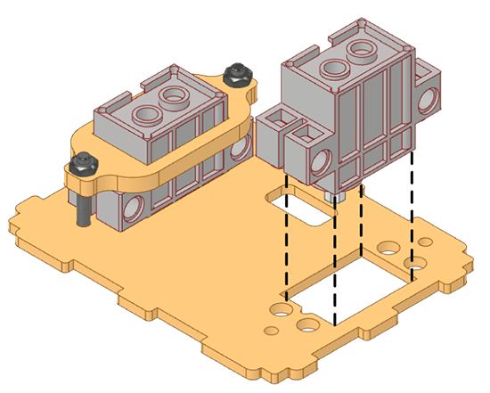
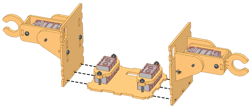
- Insert a 180° Servo Motor into the Body-Base.
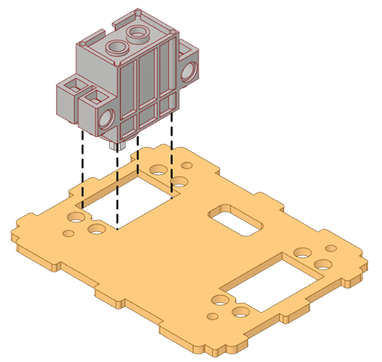 Alert: Keep the 180° Servo Motor shaft towards the notch in the servo profile.
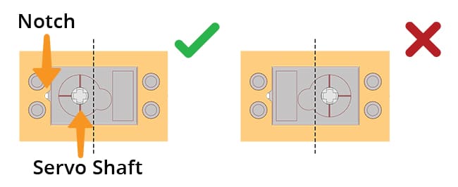
- Pass the 180° Servo Motor’s wire through the Servo-Support and secure the 180° Servo Support using M3 Bolts (20mm) and M3 Nuts.
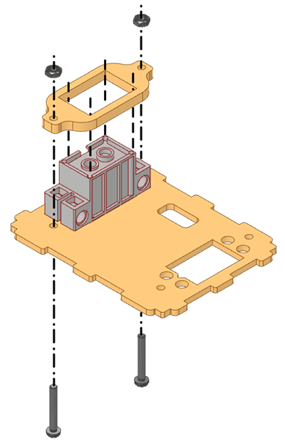
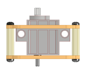
Bottom View:
- Insert another 180° Servo Motor into the Body-Base.
 Alert: Keep the 180° Servo Motor shaft towards the notch in the servo profile.
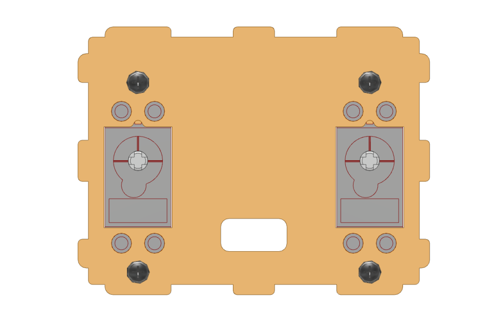
 - Pass the 180° Servo Motor’s wire through the Servo-Support and secure that 180° Servo Motor to the Body Base with the other Servo-Support using M3 Bolts (20mm) and M3 Nuts.
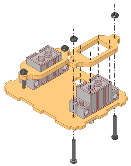
Bottom View:
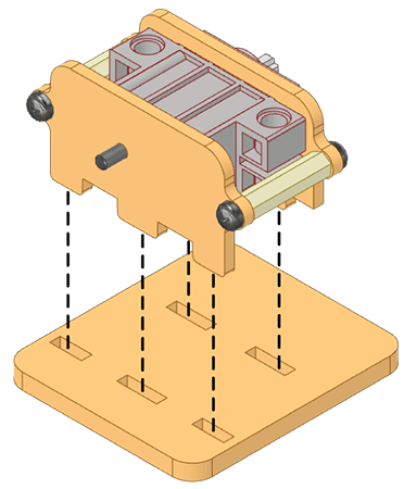
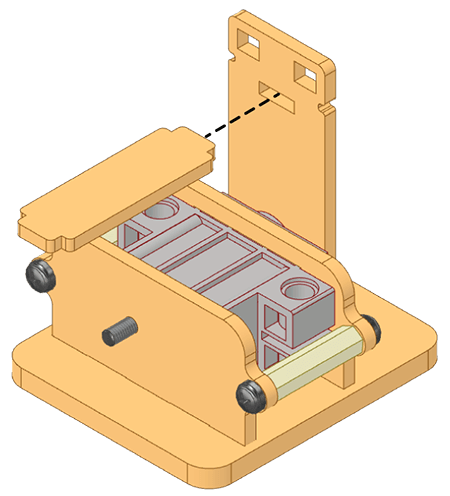
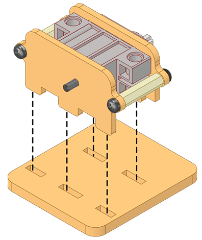
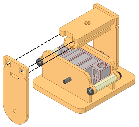
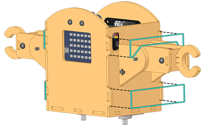
- Now attach both the Body-Sides (with the assembled arms) to the Body-Base.
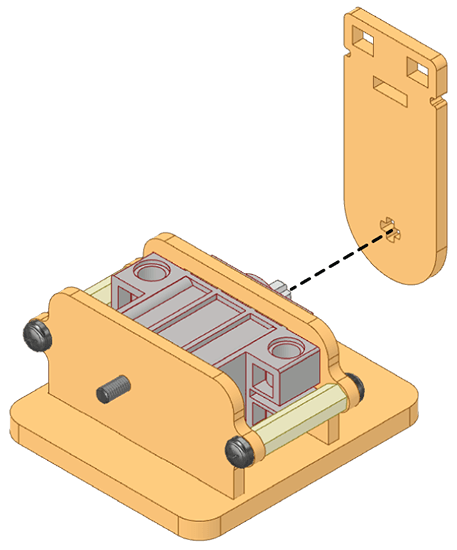
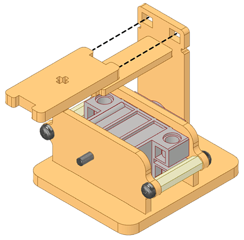
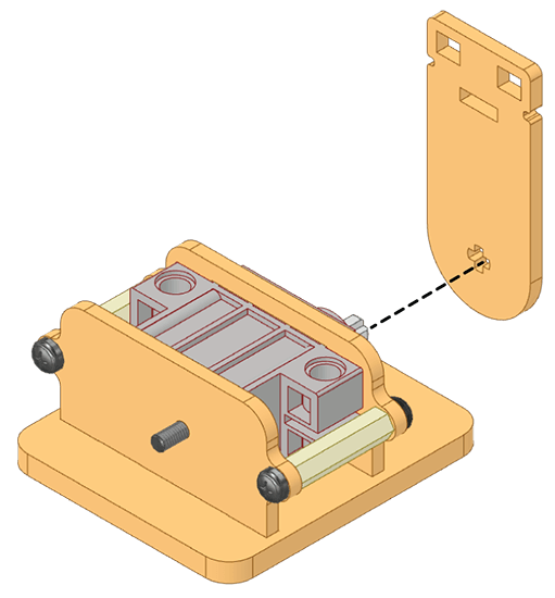
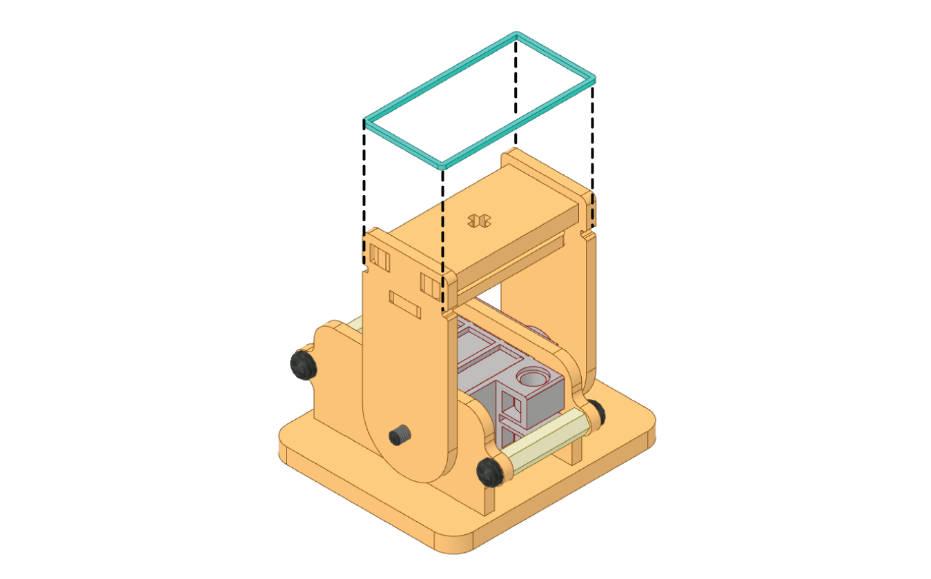
- Attach the Body-Back.
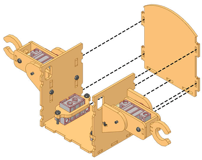
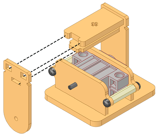
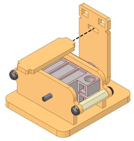
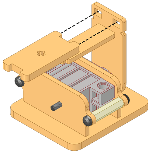
- Attach the Body-Front to the rest of the body enclosing the Quarky, the Expansion Connectors, and the 180° Servo Motor’s wires inside.
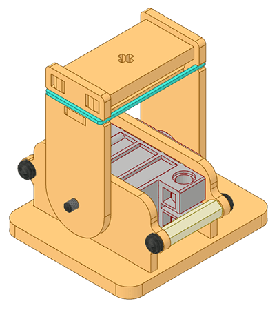
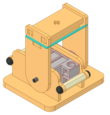
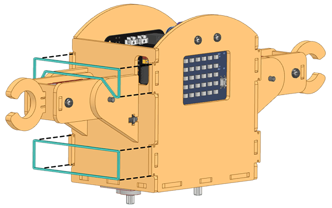
- Fix the body using Rubber bands.
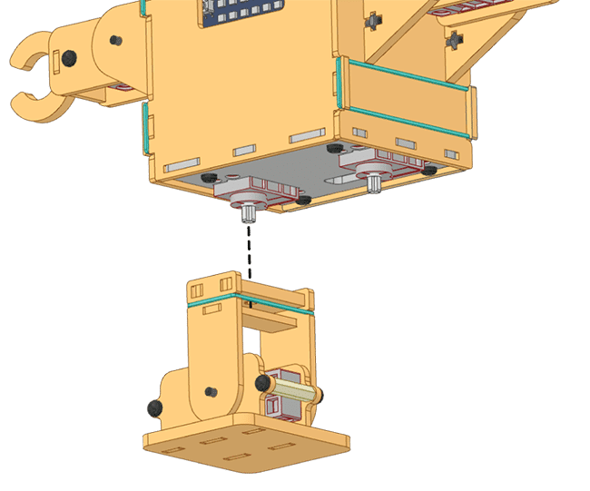
- Fix the Legs to the Body-Base.
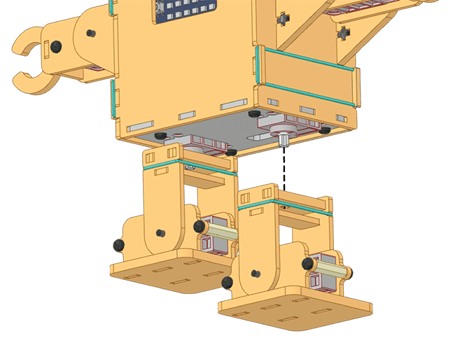 Assembled:
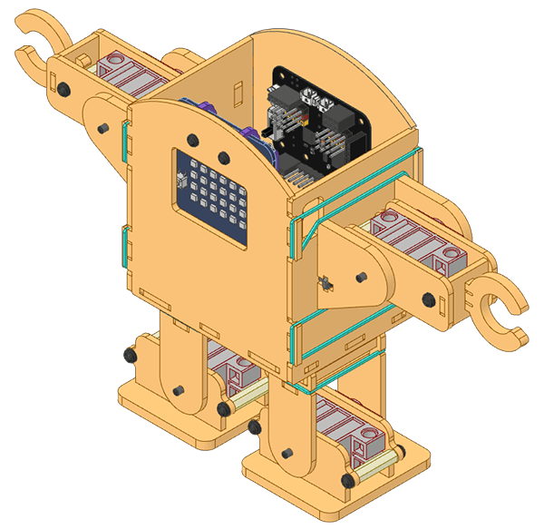
- Now manage the 180° Servo Motor’s wires from the wiring holes as shown.
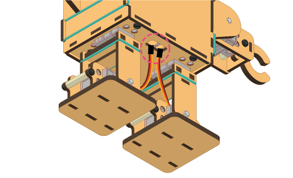
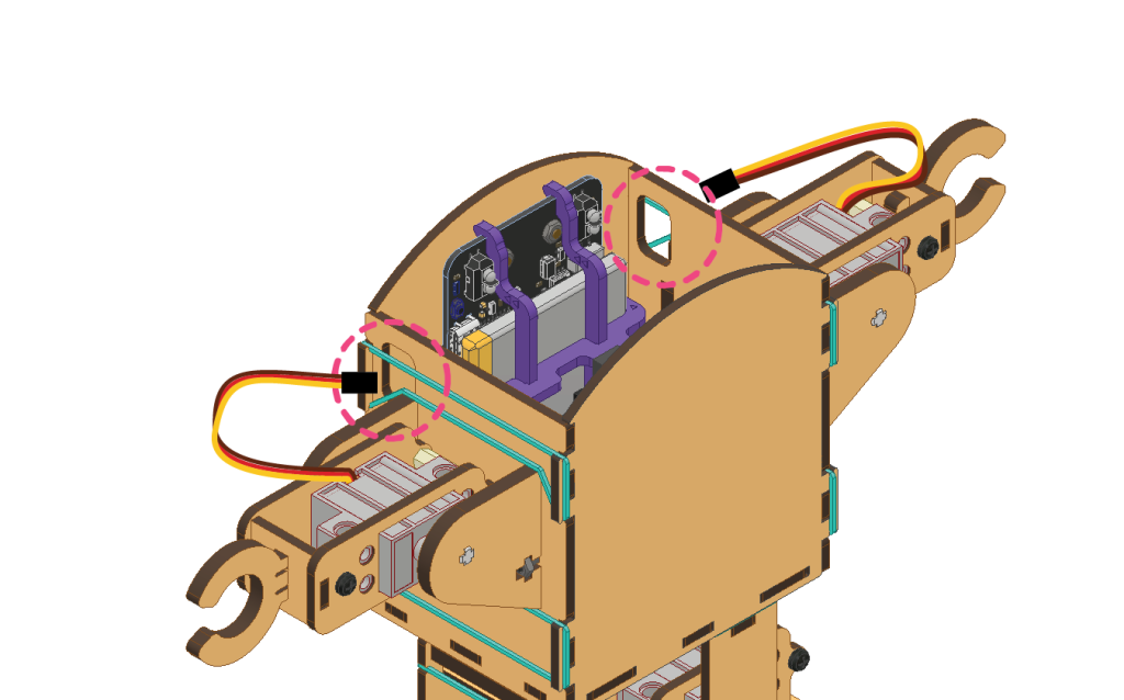
- Attach the 180° Servo Motor’s wires as shown and attach them all to the Expansion Board [refer to the wiring diagram].
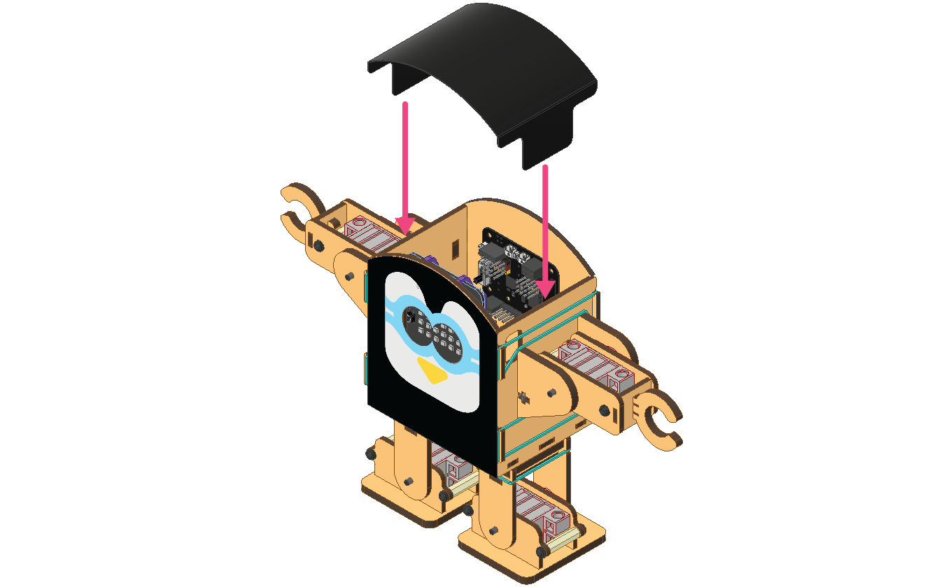
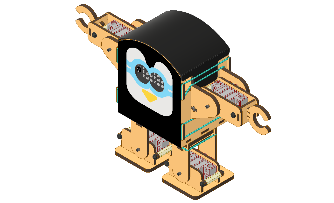
- Stick the Face Creative and Top Creative on the Humanoid body as shown.
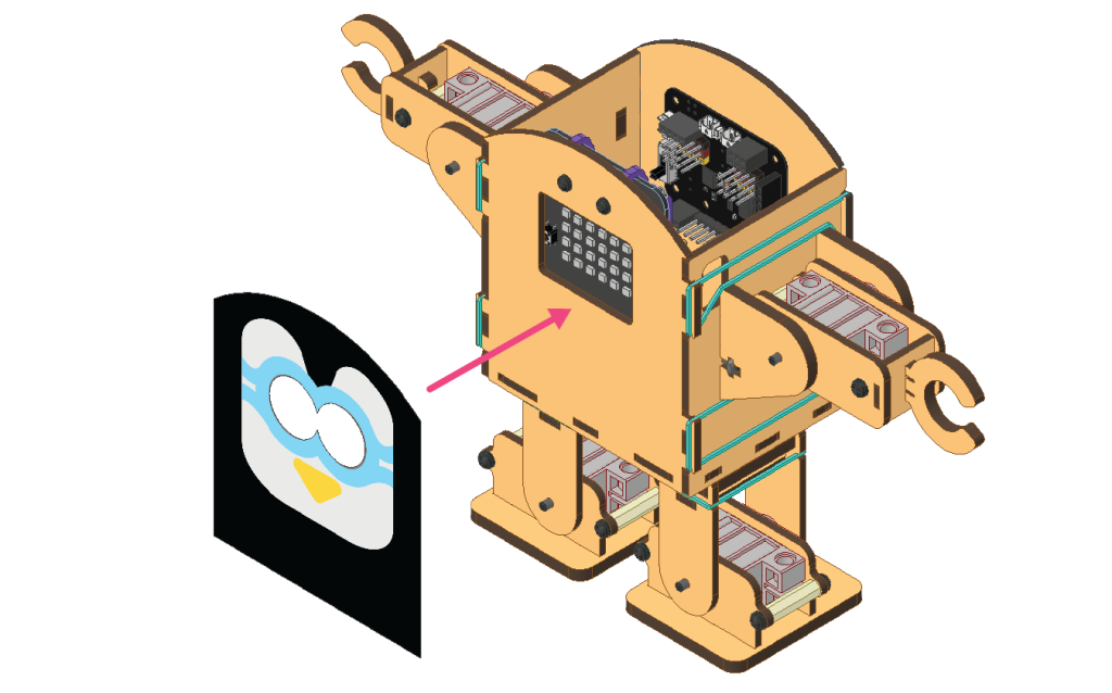
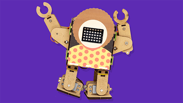
 Your Robot is ready:
Finally, the Quarky Humanoid Robot is now completely assembled. You can now program it to perform various tasks and make it walk, move its arms, and perform some cool tricks like kicking a ball or doing a dance. With the help of the PictoBlox coding platform, you can now control the robot and make it do whatever you want it to do.