
Introduction
Parties are super fun. But not that much if you’re the host! There’re so much you’ve to do: serve the drinks and food, see to it that everybody’s having a great time and that nothing runs out, and what not! Though there are some things that you have to care about, we, rather this project, can help you with one thing – serving drinks! Say hello to the robotic arm bartender, your perfect partner to keep them chilled drinks comin’! Follow step-by-step instructions to build it and program it in PictoBlox, a powerful graphical programming software with advanced capabilities.
You can download PictoBlox from HERE.
So, who’s ready to add an element of style in their party?
Ready, set, DIY!
The Cutouts
Before we start making let’s first know the name of each acrylic part. You can download the MDF designs from here.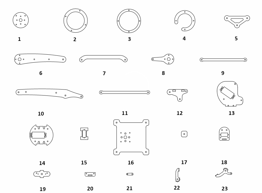
- Inner Bearing Disc
- Bottom Outer Bearing Disc
- Middle Outer Bearing Disc x 2
- Top Outer Bearing Disc
- Triangular Junction Plate
- Left Lower Arm x 2
- Left Middle Arm
- Right Lower Arm
- Right Middle Arm
- Right Upper Arm x 2
- Left Upper Arm x 2
- Right/Left Rotational Servo Plate x 2
- Right/Left Side Servo Mounting Plate x 2
- Base Servo Motor Plate
- End-Effector Rotational Micro Servo Plate
- Robotic Arm Base
- Spacers
- Gripper Part-1
- Gripper Plate
- Gripper Part-2
- Gripper Link
- Gripper Claw-2
- Gripper Claw-1
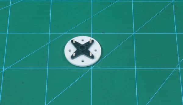
Assembly of the Base
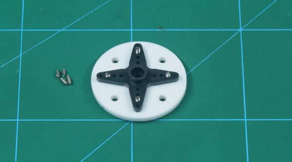
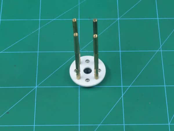
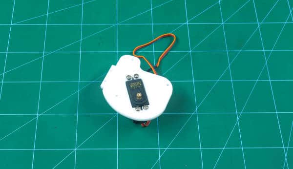
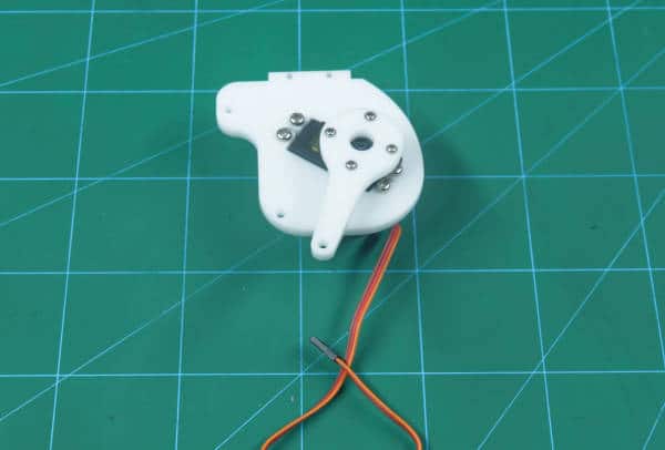
- Mount servo horn on the inner bearing disc using self-threading M2 (“M2” represents a diameter of 2mm) screws of 8mm length. These screws can be found in servo accessories. Make sure that the center of the inner bearing disc and the servo horn are aligned.
- Once you have attached the servo horn, cut the notches of all the screws.
- Now, We need four 70 mm female to female standoffs. Construct 70 mm female to female standoff using two 25mm male to female and one 20 mm female to female standoffs. Attach the standoffs on the remaining holes of the inner bearing disc using M3 bolts of 8mm length. Make sure that you attach the standoffs on the other side of the servo horn. These standoffs will be used to give height to your robotic arm. You can change the length of standoffs if you want.
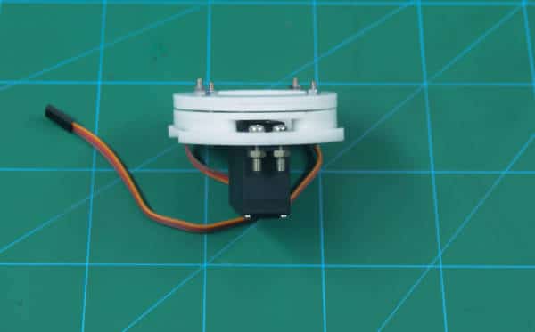
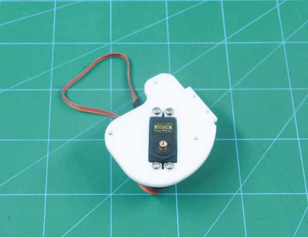
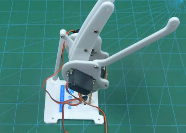
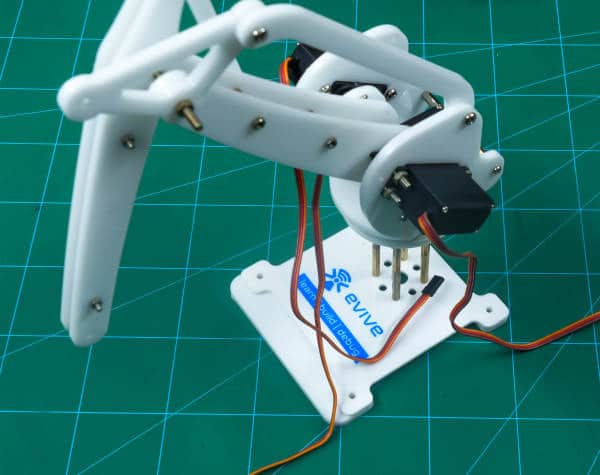
- Once done, take the metal servo and attach it on the base servo motor plate using M4 nuts and bolts.
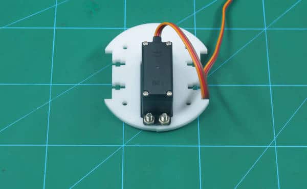
 Before we take the metal servo in use, set the angle to 90 degrees using evive’s firmware. Connect the metal servo to any of the servo channel given on evive. Switch ON evive, choose Controls, select Servos, select Servo channel (S1 or S2) and finally, set the servo angle to 90 degrees using the potentiometer.
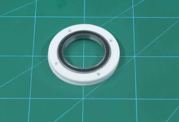
 - Take the bottom outer bearing disc and place the bearing on top of the bottom outer bearing disc.
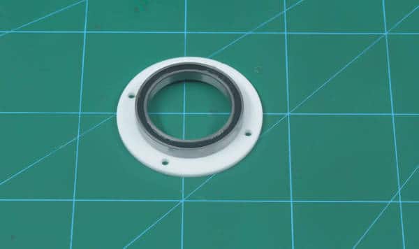
- Then, place the two middle outer bearing disc onto the bottom outer bearing disc and place the top outer bearing discs onto the middle outer bearing disc and align the holes on all the discs.
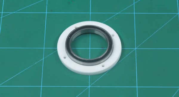
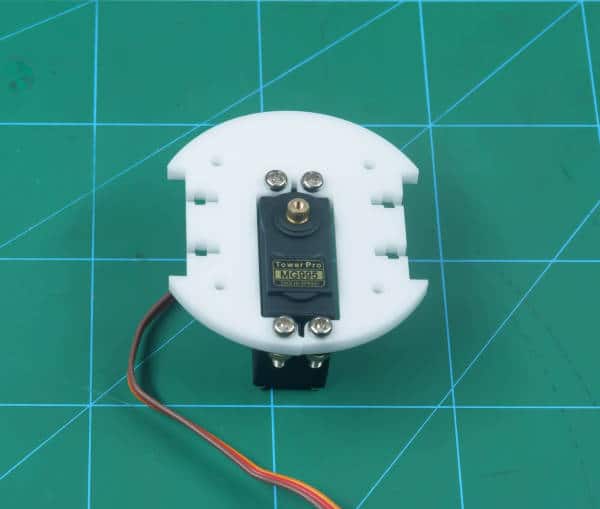
- Finally, place the base servo motor plate on the top outer bearing disc and stack all of them together using M3 bolts of 25mm length and M3 nuts.
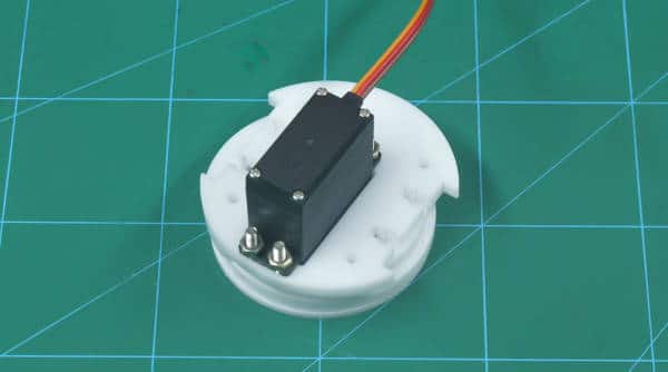
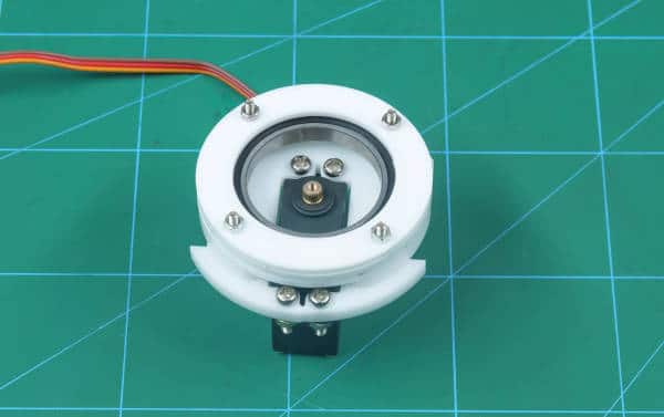
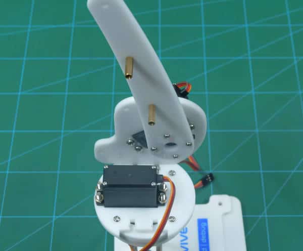
- Take this sub-assembly and attach the servo head to the servo horn attached to the inner bearing disc using the servo bolt(available in servo accessories).
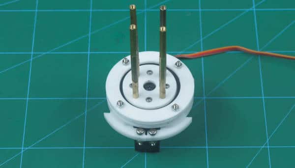
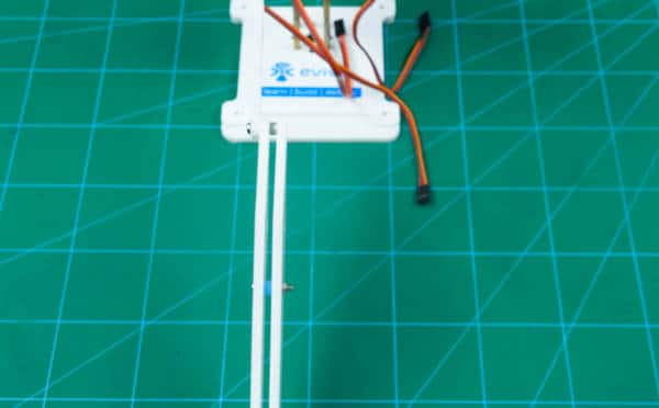
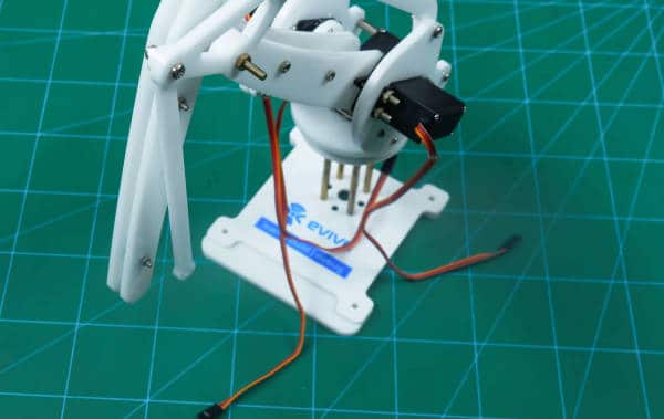
- Attach the inner bearing disc on the robotic arm base by fixing the female end of the standoffs on it using M3 bolts of length 8mm.
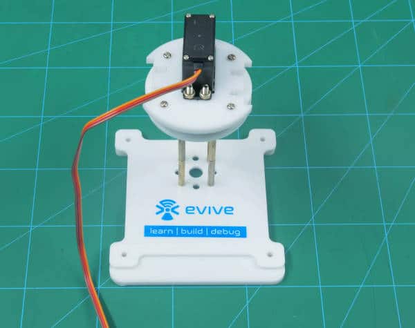 Make sure that the base servo motor plate is placed in such a way that the servo should be close to the rear end.
Making the Left Side of the Robotic Arm
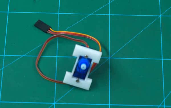
- Take the left side servo mounting plate and attach the metal servo on it using M4 nuts and bolts. Make sure that you set the servo angle to 90 degrees as done in the previous step using evive’s firmware.
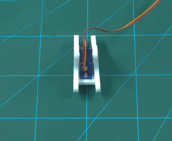
 Make sure that the servo head should always point inwards.
 - Now, take the left lower arm and attach the servo horn to it using the screws of 8mm length.
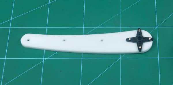 Make sure that the servo horn should be attached in such a way that curve of the left lower arm needs to be outwards.
 - Once you have attached the servo horn, cut the notches of the screws.
- Now, place the servo horn on the left metal servo head and fix it using the servo screw.
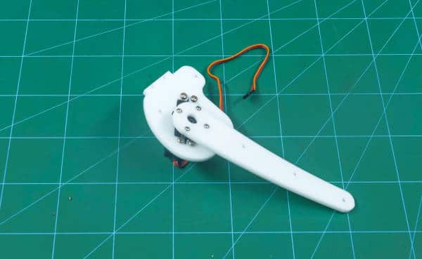
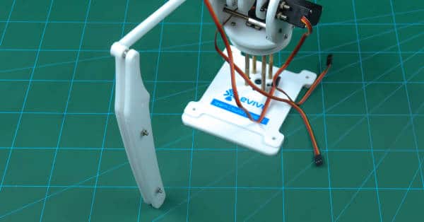
- Finally, attach the left side servo mounting plate in the holes given on the base servo motor plate using M3 bolts of 12mm length and M3 nuts.
- Once done, fix the male side of 15mm male-to-female standoffs into the left lower arm using M3 nuts as shown in the image below.
- Connect the female side of the standoffs to the left lower arm-2 using M3 bolts of 12mm length.
Making the Right Side of the Robotic Arm
- Now, take the right side servo mounting plate and attach the metal servo to it using M4 nuts and bolts. As done before, make sure that you set servo angle to 90 degrees using evive’s firmware.
 Make sure that the servo head points inwards.
 - Take the right lower arm and attach the metal servo horn to it using servo screw of 8mm length.
- Once you have attached the servo horn, cut the notches of the screw using the plier.
- Then, attach the servo horn to the servo head using the servo screw.
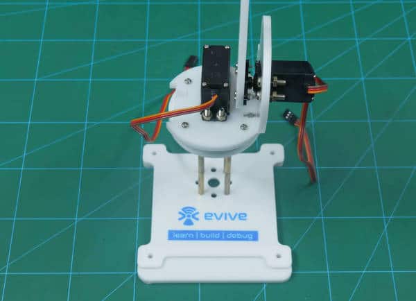
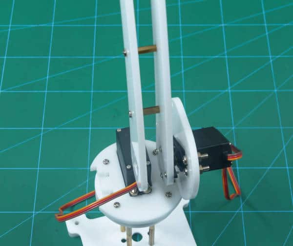
- Attach the right side servo mounting plate to the holes given in the base servo motor plate using M3 bolts of 12mm length and M3 nuts.
- Now, take two standoffs of length 50mm(25mm male-to-female + 25mm female-to-female) and attach it between the left and right side servo mounting plates using M3 bolts of 12mm length. This will let you keep both the plates together.
- Next, take the right middle arm and fix it to the right lower arm using M4 bolt and lock nut.
- Now, take the left middle arm and attach it to the left side servo mounting plate using M4 bolt and lock nut.
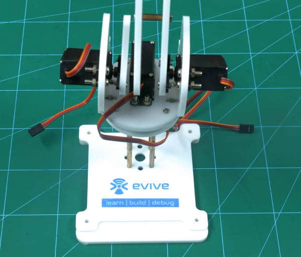
- Once done, fix the right upper arm to the right middle arm using M4 bolt and lock nut.
- Next, attach two M3 bolts of 20mm to the right upper arm in the holes given. Now, to these bolts attach the 3D printed spacers.
 Make sure that you fix the spacers inside.
 - Now, take right upper arm-2 and fix it to the right upper arm at the spacers using M3 nuts to the M3 bolts that are already attached.
- Take the triangular junction plate and attach it to the left middle arm from the left-most hole using M4 bolts and lock nut.
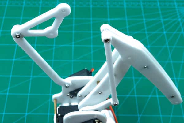
- Now, fix this triangular junction plate to the left lower arm and the right upper arm from the center hole using M4 bolts of 40mm length and nut.
- Finally, attach the left upper arm from the right-most hole on the triangular junction plate using M4 bolt and lock nut.
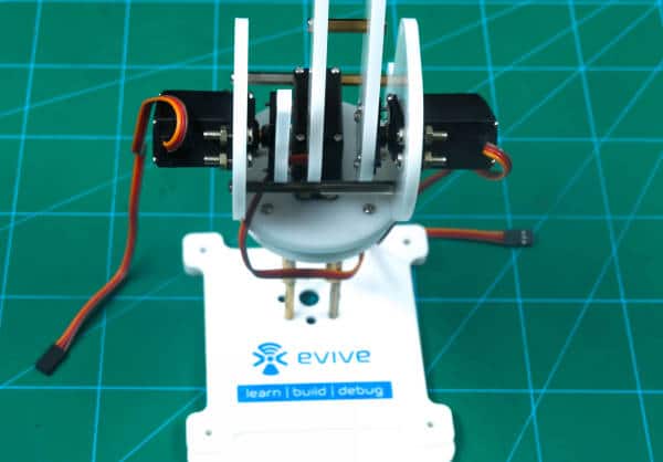
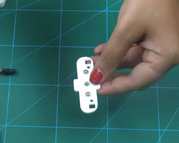
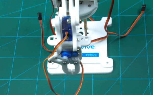
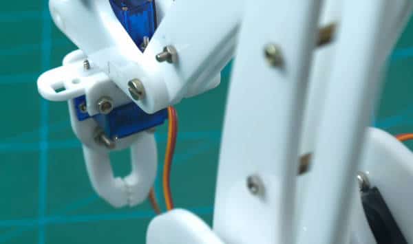
- Take the end-effector rotational micro servo plate and fix the micro servo to it using M2 nuts and bolts.
 Before you use the micro servo, make sure that you have set the servo angle to 90 degrees.
 - Simply fix the right rotational servo plate and the left rotational servo plate to the end-effector rotational micro servo plate.
- Fix this sub-assembly of the rotational servo plates and attach to the right upper arms using M4 bolt of length 20mm and lock nut.
- Next, attach the free side of the left upper arm to the left rotational servo plate using M4 bolt and lock nut
Now, all we need to make is the gripper assembly.
Making the Gripper Assembly
Its time to make the gripper assembly that will hold the ice in our case and place it into the glasses. You can use the gripper for anything you want. Let’s begin.
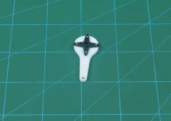
- Take the micro servo horn and attach on to the gripper plate using servo screws.
- Finally, fix the gripper plate on to the rotational micro servo head using the servo screw.
Assembly of the Gripper Claw
- Insert micro servo into the slot on the gripper part 1 using M2 bolts of 8mm length and M2 nuts.
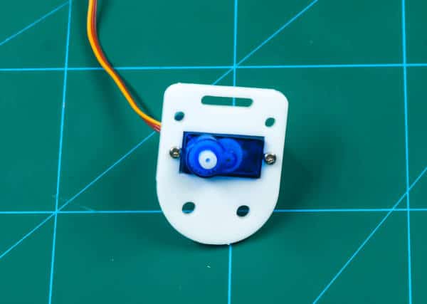
- Make sure you set the servo angle to 90 degrees using evive’s firmware.
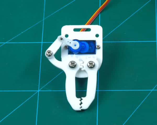
- Fasten gripper link to the one-sided micro servo horn using a self-threading screw from micro servo accessories. Keep in mind, protruded end of servo horn should be facing the servo.
- Bring together gripper link and one-sided micro servo horn and attach them on to the servo head using servo screw.
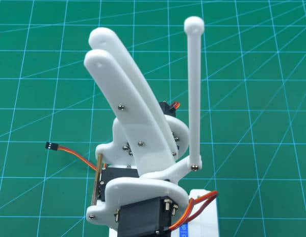
- Next, insert the M3 bolt of 12mm length to gripper claw 1. Hold the “gripper link and servo horn” assembly intact. Then insert gripper link 1 onto this bolt and fasten an M4 nut on the same. Ensure that the links are movable about the bolt but they shouldn’t be too loose.
- Now, note that there is a free hole on the gripper part 1 and that gripper claw 1 is in front of the other hole. Intuitively, place gripper claw 2 on the other hole. Now, M4 bolts of 16mm length in both these holes and fasten using M4 lock nuts. Keep in mind that claws aren’t too loose but are free to rotate about these bolts.
- Insert gripper plate into the thin slot provided on the gripper part 1. Note that this part is not symmetric and the small square slots are nearer to one end than to the other. Do insert this in the exact configuration
- Fasten 15mm standoffs to the plate using M3 bolts of 8mm length. Slide gripper part 2 (with a thin slit) onto the protrusion on gripper plate.
- Notice that gripper part 2 has holes 3mm in diameter so that threaded part of standoffs may pass through it. Fasten these parts using M3 nuts.
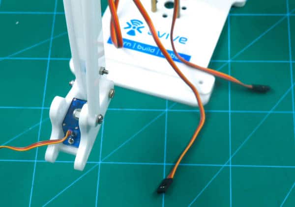
Making the Connections
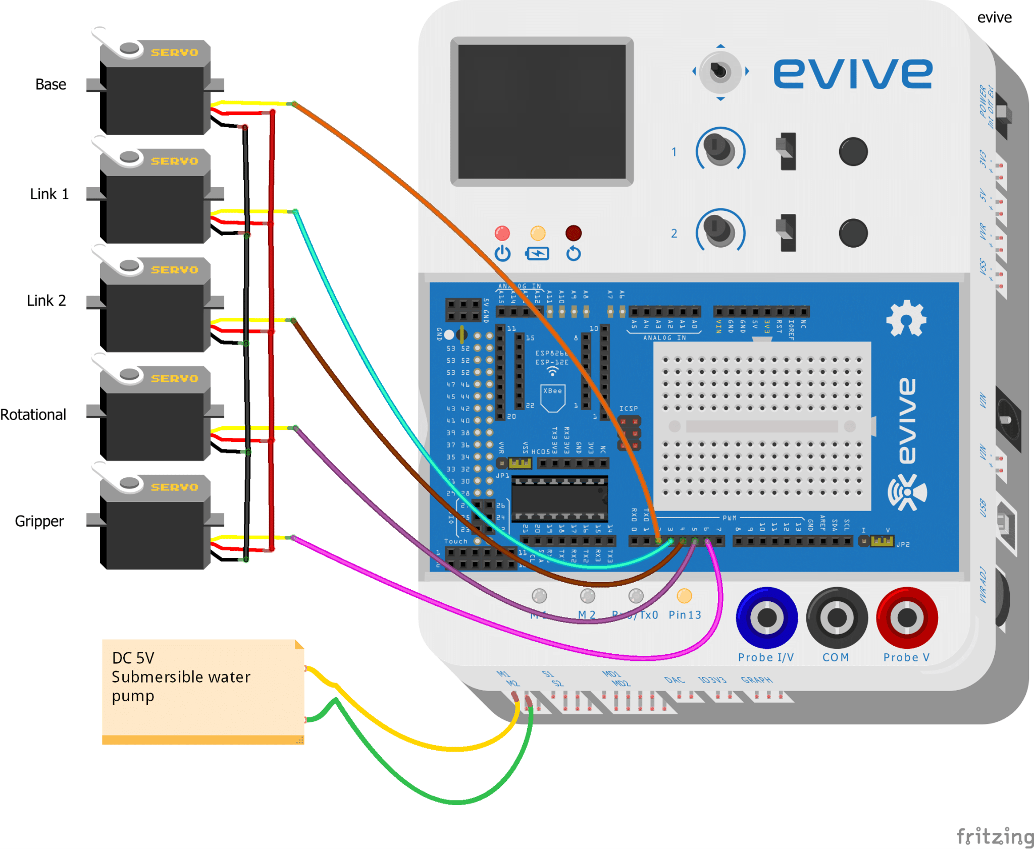
Make the connections as shown in the below image:
Servos:
- Base servo:
- VCC (Red wire): 5V of evive
- GND (Brown wire): GND of evive
- Signal (Orange wire): Digital pin 2 of evive
- Link 1/ Left servo:
- VCC (Red wire): 5V of evive
- GND (Brown wire): GND of evive
- Signal (Orange wire): Digital pin 3 of evive
- Link 2/ Right servo:
- VCC (Red wire): 5V of evive
- GND (Brown wire): GND of evive
- Signal (Orange wire): Digital pin 4 of evive
- Rotational servo:
- VCC (Red wire): 5V of evive
- GND(Brown wire): GND of evive
- Signal (Orange wire): Digital pin 5 of evive
- Gripper servo:
- VCC (Red wire): 5V
- GND (Brown wire): GND
- Signal (Orange wire): Digital pin 6 of evive
Water Pump: M1 channel of evive
Working of the Robotic Arm Bartender
The arm will first pick the ice cube from the bowl, reach the coordinates of the first glass drop it. Again travels back to pick up the second ice cube, and again drops it into the first glass. Now, the entire process will be repeated for the other glass. You can change the number of ice cubes that the robotic arm will drop in each glass.
We first need to find out the X, Y, Z coordinates of the places where you want to place the glasses and ice bucket. You can find the coordinates with the help of the go to x (), y (), z () in () ms block.
You can try setting the coordinates in real time or stage mode. But before working in the stage mode upload its firmware by uploading the following code to evive.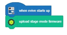
Once coded, the robotic arm automatically reached the given place.
As we know, our robotic arm will even serve the ices in the glasses using the gripper. Thus, we will set the open and close gripper angle for each time the robotic arm reaches the ice bowl or the glasses. We will drop two ice cubes into each glass.
Once, the ice cubes are dropped, it’s time to serve the drink. We have submerged our submersible pump into a big jar filled with drinks. And have placed the pipe onto the robotic arm whose opening can be placed near the gripper. As soon as the ice cubes are dropped, the robotic arm again reaches to glass 1 and start the pump and offs the pump according to the duration set by us in the code. Now, it will fill the glass-2.
To fill the glasses, we need to find out how much time will the pump take to fill one glass. Once you get the time, turn on and off the pump for that duration (EX: In our case, the pump takes 7sec to fill each glass).
Note: you can change the number of ice cubes, glasses, and the duration to keep your pump ON.
Thus, this is how our robotic arm will serve the drinks.
PictoBlox Code
We are going to write our code in PictoBlox: graphical programming platform.
The first block is the main block that will initialize the entire process.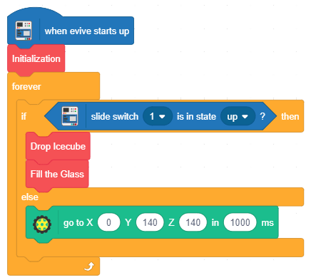
This block is used to initialize all the servos.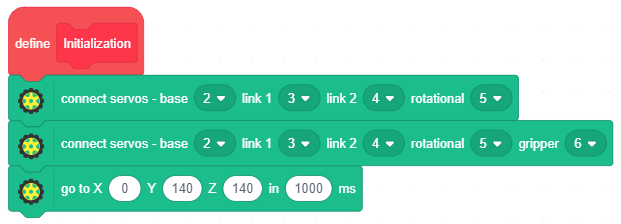
This block mainly is used to drop the picked ice cubes into the glasses.
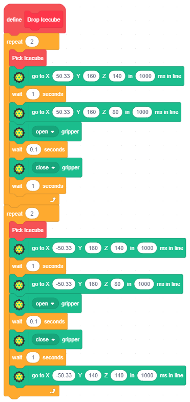
The block below is actually the one that lifts up the ice cube from the bowl. The gripper will close and open the claw according to the instructions given in this block.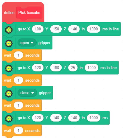
This block helps the robotic arm travel from glass-2 to glass-1 and back to glass-2 and calls the function to control the submersible pump.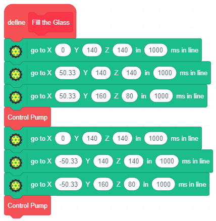
The block below is used to ON and OFF the submersible pump which will pour the liquid into the glasses.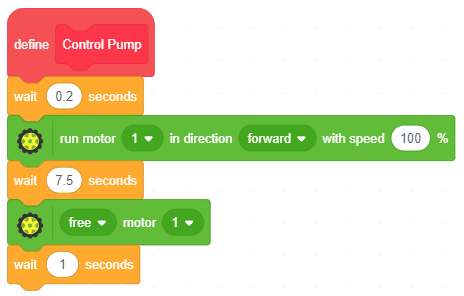
Conclusion
With this, your robotic arm bartender is ready to serve drinks in style!


 1-18 screenshot")


