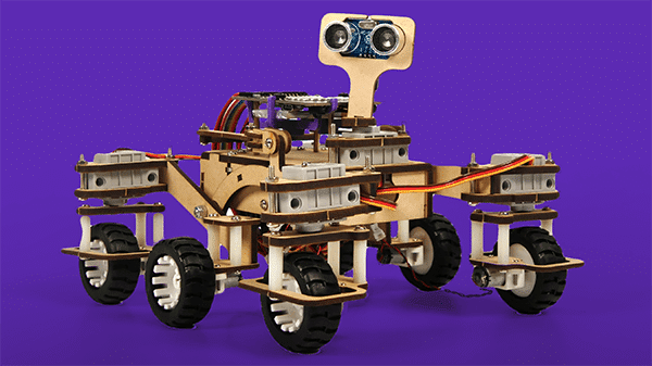
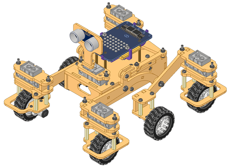
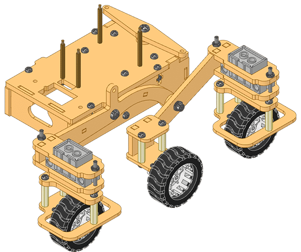
We are going to follow the steps in this lesson to assemble the Quarky Mars Rover.
Servo Initialization
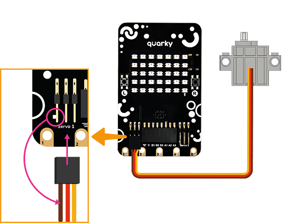
Firstly we need to calibrate the servo motors, i.e., we need to first set all eight of them to 90 degrees. This will ensure that the angle of each servo motor is properly aligned. Follow the steps:
- Connect the first servo motor to the first Quarky Servo Connector, ensuring that the brown wire is on the left side.
- Connect Quarky to your laptop using a USB cable.
- Open PictoBlox on your desktop. After that, select Block Coding as your coding environment.

- Then, click the Board button in the toolbar and select Board as Quarky.

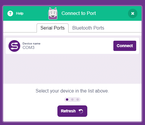
- Next, select the appropriate Serial port if the Quarky is connected via USB or the Bluetooth Port if you want to connect Quarky via Bluetooth and press Connect.
- Quarky is now connected to PictoBlox. Create the following script:

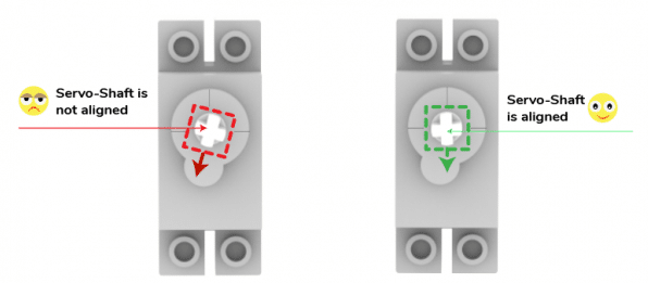
- Click on the green flag over the stage to run the script. You will find that the servo motor shaft gets perfectly aligned.
- Remove the servo motor from Quarky and repeat the process for all 5 servos.
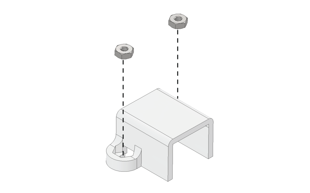
- In case the Motor Bracket does not have two M2 Nuts inserted in them already, please insert them in the following manner.

Central Body Assembly
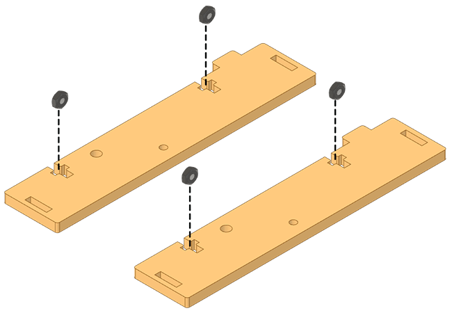
- Insert M3 Nuts in the slots of the Body Long Sides.
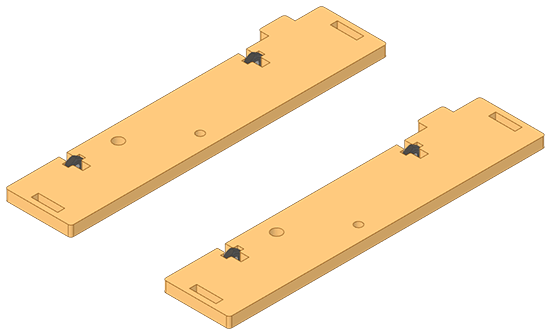
- Attach M3 Metal Spacer (60mm) on a Body Long Side using M3 Bolt (8mm).
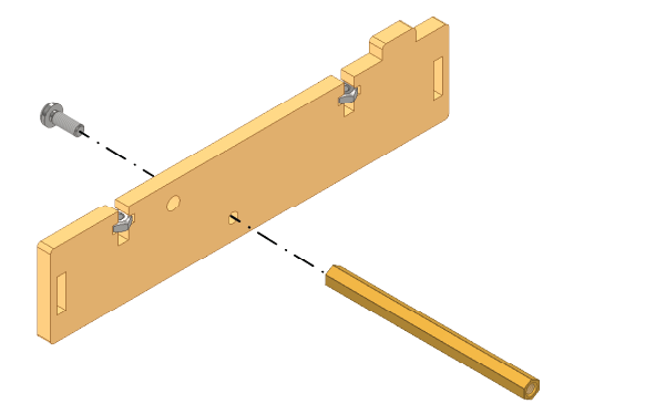
- Insert the two Body Short Sides into the Body Long Side from the same direction as the M3 Metal Spacer (60mm).
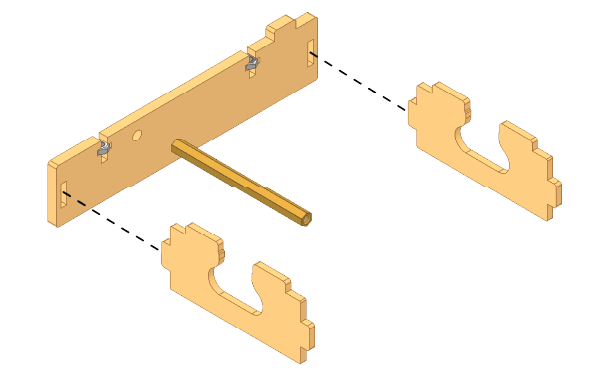
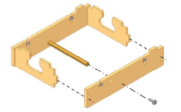
- Make a frame by attaching Body Long Side to Body Short Sides and secure it with an M3 Bolt (8mm).
- Attach four M3 Spacers (20mm) to the back side of the Body Top using M3 Bolts (8mm).
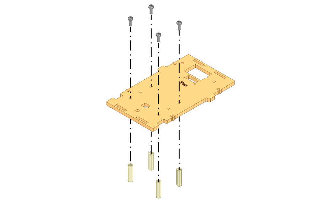
- Next, attach the Body Top to the frame. Secure the Body Top to the Body Long Sides of the frame using M3 Bolts (12mm).

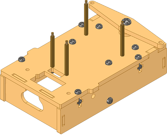
Completed Subassembly:
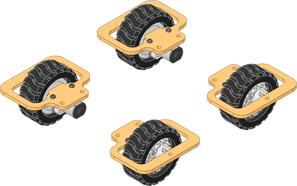
FRONT AND REAR WHEEL ASSEMBLIES
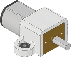
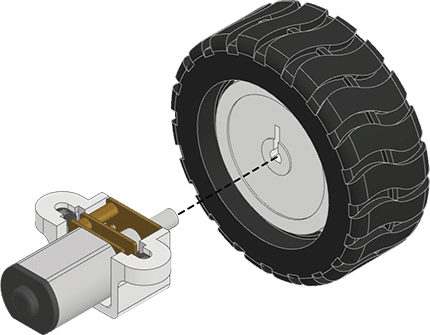
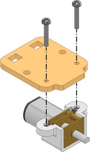
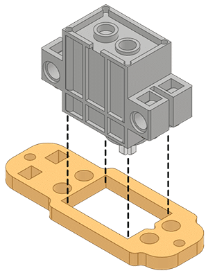
- Slide the Motor into Motor Bracket.
 Note: Ensure during the assembly that the orientation of the Motor’s cable is towards the top non-clamping side of the Motor Bracket.
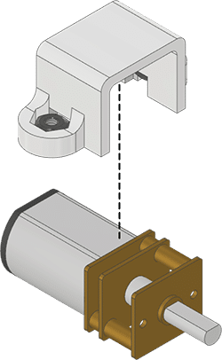
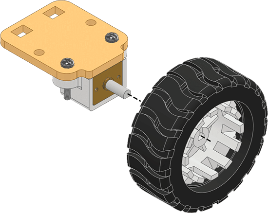
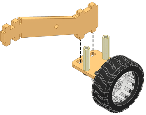
- Fix the Wheel from its backside to the Motor.
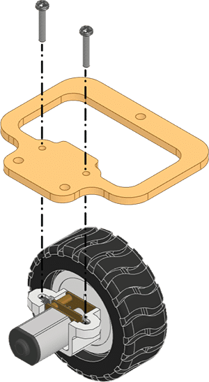
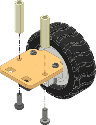
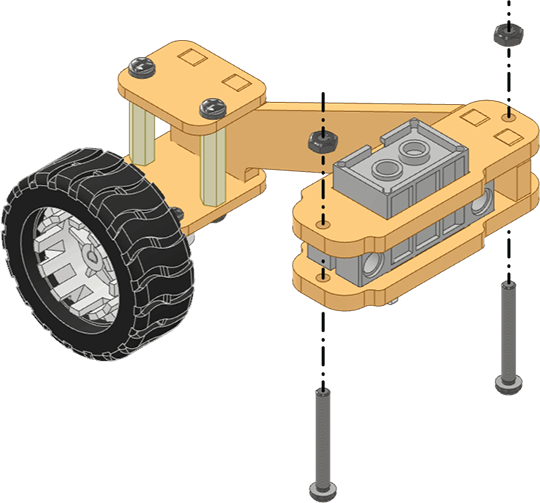
- Fix this assembly on the Wheel Frame using M2 Bolts (12mm).
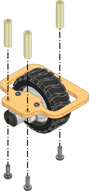
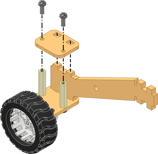
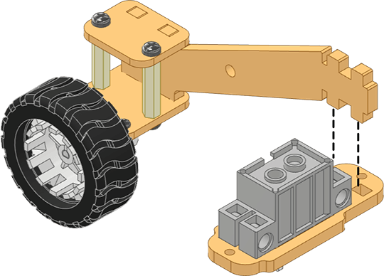
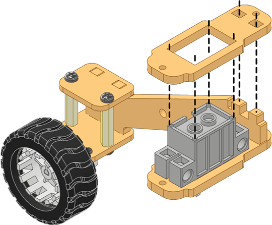
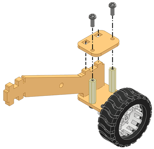
- Fix three M3 Spacers (20mm) on the top side of the Wheel Frame opposite to the Motor using M3 Bolts (8mm).
- Fix a Servo Coupling on the M3 Spacers (20mm) using M3 Bolts (8mm).
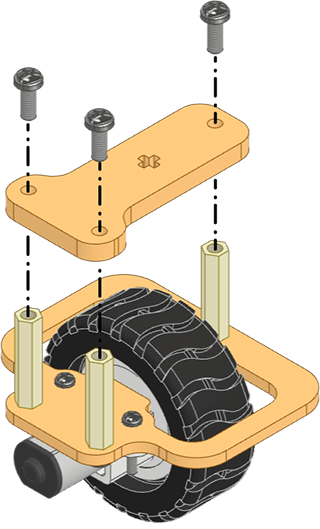
- Now repeat steps 8 to 12 three times to create four such Wheel Assemblies.
LEFT ROCKER BOGIE ASSEMBLY
LEFT BOGIE ASSEMBLY
- Slide the Motor into Motor Bracket.
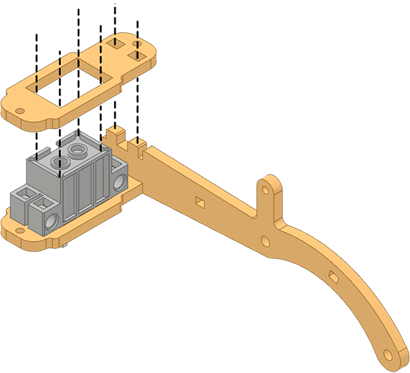
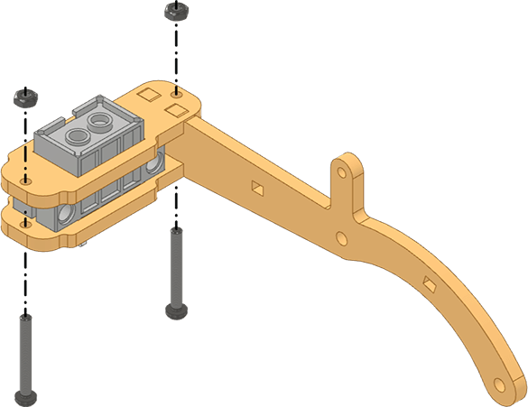
- Fix the assembly on the back side of the Motor Holder using M2 Bolts (12mm).
- Fix the Wheel from its backside to the Motor.
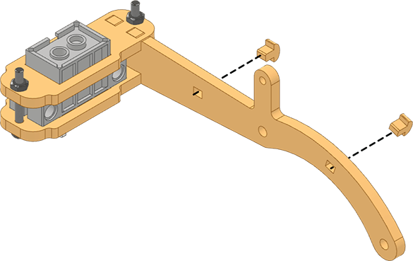
- Fix two M3 Spacers (20mm) on the side of the Motor Holder opposite to the Motor using M3 Bolts (6mm).
- Insert the lower front teeth of Link 1 (L) into the Motor Holder.
Note: While joining, ensure that the Wheel should be on L side.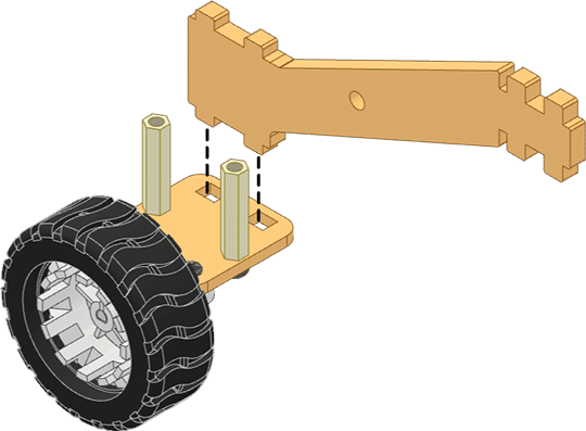
- Attach the Link Clamp to the lower front teeth of Link 1 (L) and fix it on the M3 Spacers (20mm) using M3 Bolts (6mm).
- Insert a 180° Servo Motor from its shaft side into Servo Upper Clamp B.
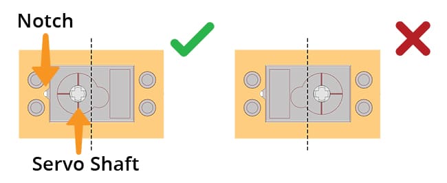
 Alert: the 180° Servo Motor’s shaft towards the notch in the servo profile.
- Insert the lower rear teeth of Link 1 (L) into Servo Upper Clamp B from the same side as 180° Servo Motor was inserted.
Note: While joining, ensure that the Servo should be on the ‘L’ side. - Insert the upper rear teeth of Link 1 (L) into Servo Lower Clamp B.
Note: Pass the cable of the 180° Servo Motor through the rectangular slot in the Servo Clamp. - Insert two M3 Bolts (20mm) in Servo Upper Clamp B and secure the 180° Servo Motor and Link 1 (L) using M3 Nuts.
Complete: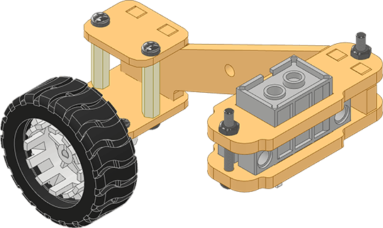
LEFT ROCKER ASSEMBLY
- Insert a 180° Servo Motor from its shaft side into Servo Upper Clamp A.Alert: Keep the 180° Servo Motor’s shaft towards the notch in the servo profile.
- Insert the lower front teeth of Link 2 (L) into Servo Upper Clamp A.
Note: While joining, ensure that the 180° Servo Motor should be on the ‘L’ side.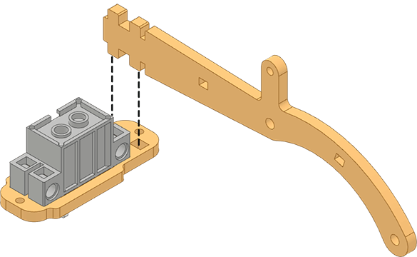
- Place Servo Lower Clamp A over the Servo Motor & fit it into the upper front teeth of Link 2 (L).Note: Pass the cable of the 180 Servo Motor through the rectangular slot in the Servo Clamp.
- Insert two M3 Bolts (20mm) in Servo Upper Clamp A and secure the 180° Servo Motor and Link 2 (L) using M3 Nuts.
- Insert two T Spacers from the right side of Link 1 (L).
Complete: 
LEFT ROCKER TO LEFT BOGIE PIVOT ASSEMBLY
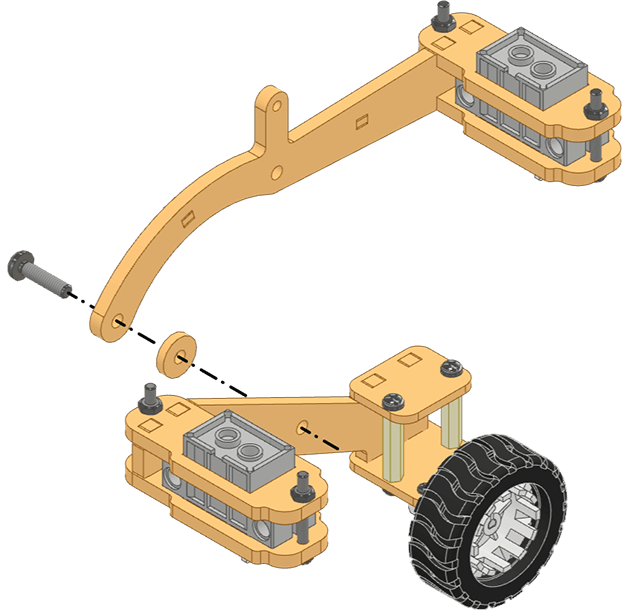
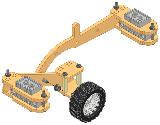
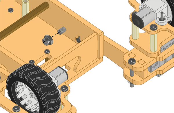
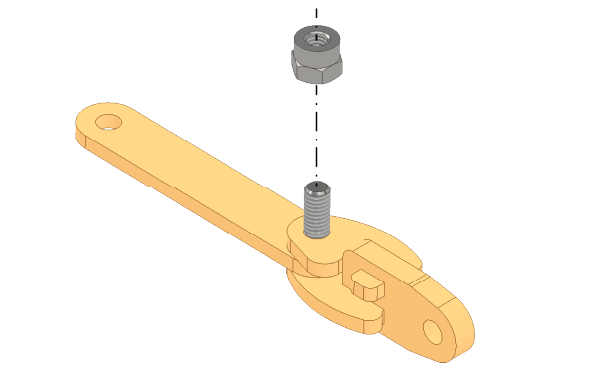
- Insert M4 Bolt (25 mm) through the Rocker, an M4 Penta Spacer, and then Bogie in this order.
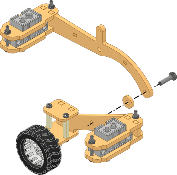
- Fix the Rocker and Bogie assemblies using M4 Lock Nut.
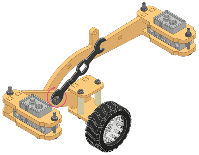
- Use the M4 Spanner to hold the M4 Lock Nut while fixing the M4 Bolt (25mm) with the screwdriver.
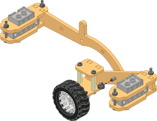
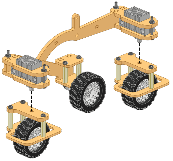
 Once everything is fitted together, slightly loosen the M4 Bolt (25 mm) to allow the Rocker and Bogie to rotate freely.
 - Attach the Front and Rear Wheel Assemblies to the shaft of the servos in the Left Rocker and Left Bogie.
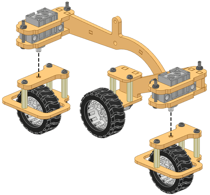 Note: Please ensure that all three motor shafts should point towards the same direction.
Complete: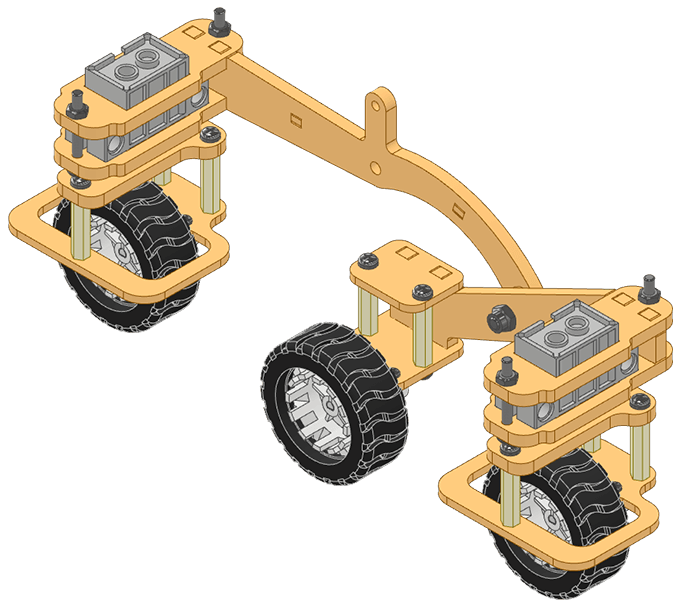
LEFT ROCKER BOGIE PIVOT ASSEMBLY
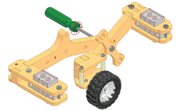
- Insert M4 Bolt (25mm) into Link 1 (L), M4 Circular Spacer and the left Body Long Side of the Central Module from the left side.
- Fix the Rocker and Bogie assemblies using M4 Lock Nut.
- Use the M4 Spanner to hold the M4 Lock Nut while fixing the M4 Bolt (25mm) with screwdriver.
Once everything is fitted together, slightly loosen the M4 Bolt (25 mm) to allow the Rocker & Bogie to rotate freely on the Central Module.
Complete:
RIGHT ROCKER BOGIE ASSEMBLY
Right Bogie Assembly
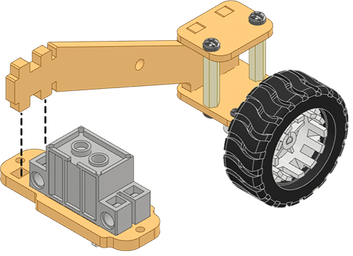
- Insert the Motor into Motor Bracket and slide it until its metal gears are covered.
- Fix the assembly onto the Motor Holder using M2 Bolt (12mm).
- Attach the Wheel from its backside to the Motor.
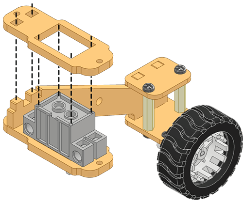
- Fix two M3 Spacers (20mm) on the side of the Motor Holder opposite to the Motor using M3 Bolts (6mm).
- Insert the lower front teeth of Link 1 (R) into the Motor Holder.
Note: While joining, ensure that the Wheel should be on the ‘R’ side.
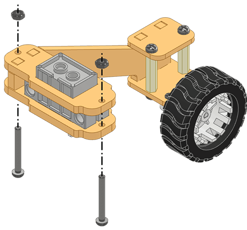
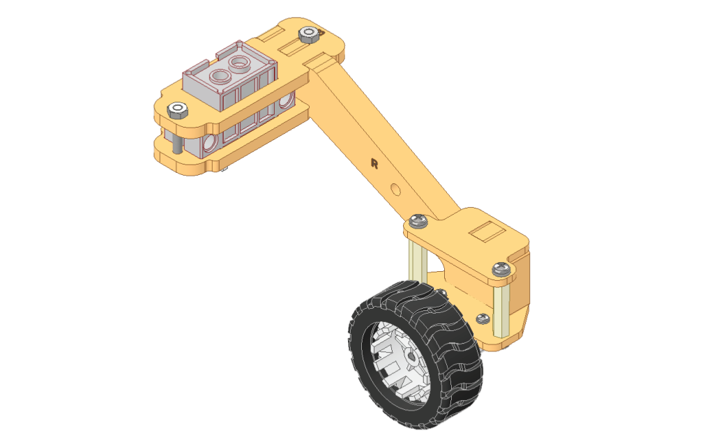
- Attach Link Clamp to the upper front teeth of Link 1 (R) and fix it on the M3 Spacers (20mm) using M3 Bolts (6mm).
- Insert a 180° Servo Motor from its shaft side into Servo Upper Clamp B.
Alert: Keep the 180° Servo Motor’s shaft towards the notch in the servo profile.
- Insert the lower rear teeth of Link 1 (R) into Servo Upper Clamp B from the same side as 180° Servo Motor was inserted.
Note: While joining, ensure that the Servo should be on the ‘R’ side.
- Insert the upper rear teeth of Link 1 (R) into Servo Lower Clamp B.
Note: While joining, ensure that the Servo should be on the ‘R’ side.
-
Insert two M3 Bolts (20mm) in Servo Upper Clamp B and secure the 180° Servo Motor and Link 1 (R) using M3 Nuts.
RIGHT ROCKER ASSEMBLY
- Insert a 180° Servo Motor from its shaft side into Servo Upper Clamp A.Alert: Keep the 180° Servo Motor’s shaft towards the notch in the servo profile.

- Insert the lower front teeth of Link 2 into Servo Upper Clamp A.Note: While joining, ensure that the 180° Servo Motor should be on the ‘R’ side.
- Insert the upper front teeth of Link 2 into Servo Lower Clamp ANote: Pass the cable of the 180° Servo Motor through the rectangular slot in the Servo Clamp.
- Insert two M3 Bolts (20mm) in Servo Upper Clamp A and secure the 180° Servo Motor and Link 2 (R) using M3 Nuts.
- Insert two T Spacers on the left side of Link 1 (R).
Complete:

RIGHT ROCKER TO RIGHT BOGIE PIVOT ASSEMBLY
- Insert M4 Bolt (25mm) through the Rocker, an M4 Penta Spacer, and the Bogie in this order.
- Fix the Rocker and Bogie assemblies using M4 Lock Nut.
- Use the M4 Spanner to hold the M4 Lock Nut while driving the M4 Bolt (25mm) with a screwdriver.
Once completely in, loosen the M4 Bolt (25mm) a little so that the Rocker and Bogie rotate smoothly. - Attach the Front and Rear Wheel Assemblies to the shaft of the servos in the Right Rocker and Right Bogie.
 Note: Pass the cable of the 180° Servo Motor through the rectangular slot in the Servo Clamp.
Complete:

ROCKER BOGIE PIVOT ASSEMBLY
- Insert M4 Bolt (25mm) into Link 1 (R), M4 Circular Spacer and the right Body Long Side of the Central Module from Right Side.
- Fix the Rocker and Bogie assemblies using M4 Lock Nut.
- Use the M4 Spanner to hold the M4 Lock Nut while fixing the M4 Bolt (25mm) with the help of a screwdriver.
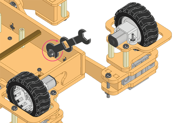
Once completely in, loosen the M4 Bolt (25mm) a little so that the Left Rocker Bogie rotates smoothly about the Pivot on the Central Module.
Complete:

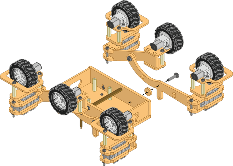
DIFFERENTIAL SUSPENSION ASSEMBLY
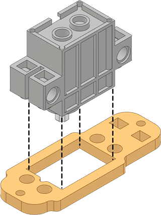
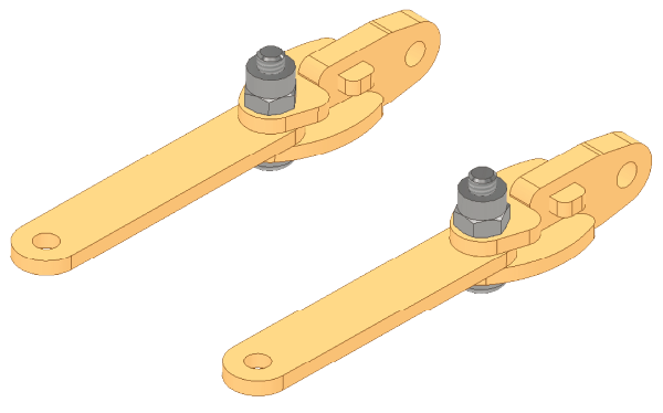
- Insert two Differential Connector 2 in the narrow slots of the Differential Connector 1.

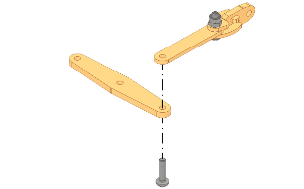
- Insert a M4 Bolt (12mm) through the Differential Connector Assembly and Differential Link.

- Fix the Assembly using M4 Lock Nut. Use the M4 Spanner to hold the M4 Lock Nut while fixing the M4 Bolt (12mm) with a screwdriver.

Once completely in, loosen the M4 Bolt (12mm) a little so that the Differential Link and Differential Connector rotates smoothly. - Repeat steps 58-60 for another Differential Link Assembly.
- Insert a M4 Bolt (12mm) through the Differential Bar and Differential Link.
- Fix the Differential Link and Differential Bar using M4 Lock Nut. Use the M4 Spanner to hold the M4 Lock Nut while fixing the M4 Bolt (12mm) with screwdriver.


- Repeat steps 61-62 to attach another Differential Link to the other end of the Differential Bar.


Once completely in, loosen the M4 Bolt (12mm) a little from both sides so that the Differential Link and Differential Connector rotates smoothly.
Complete:
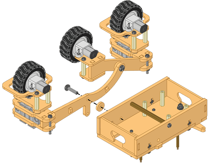
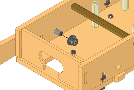
- Insert an M4 Bolt (25mm) through the Differential Bar, two M4 Circular Spacers, and the Base Top. Lock the assembly using M4 Lock Nut.

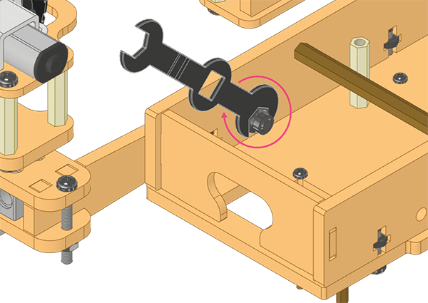
- Use the M4 Spanner to hold the M4 Lock Nut while fixing the M4 Bolt (25mm) using screwdriver.
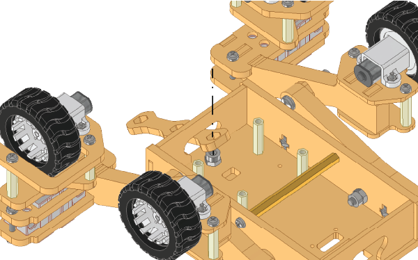

Once completely in, loosen the M4 Bolt (25mm) a little so that the Differential Link and Differential Connector rotates smoothly. - Attach Differential Connector to the Right Side of Rocker with M4 Bolt (20mm). Lock the assembly using M4 Lock Nut.
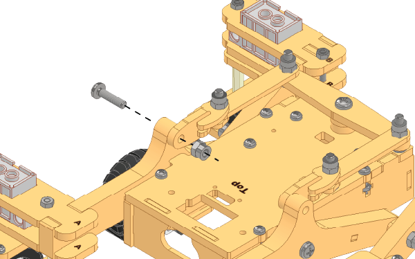
- Use the M4 Spanner to hold the M4 Lock Nut while fixing the M4 Bolt (20mm) with screwdriver.

Once completely in, loosen the M4 Bolt (20mm) a little so that the Differential Link and Differential Connector rotates smoothly. - Repeat steps 66-67 to attach Differential Connector on the Left Side of the Rocker.


Once completely in, loosen the M4 Bolt (20mm) a little so that the Differential Link and Differential Connector rotates smoothly. - Place 180° Servo Motor into its slot on the Body Top Ensure that all the cables go through the slot.
Alert: Keep the 180° Servo Motor’s shaft towards the notch in the servo profile.
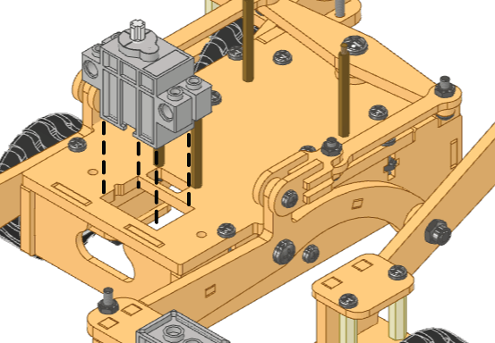
- Attach the Servo Holder on top of 180° Servo Motor using M3 Bolts (20mm) and M3 Nuts.
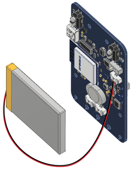
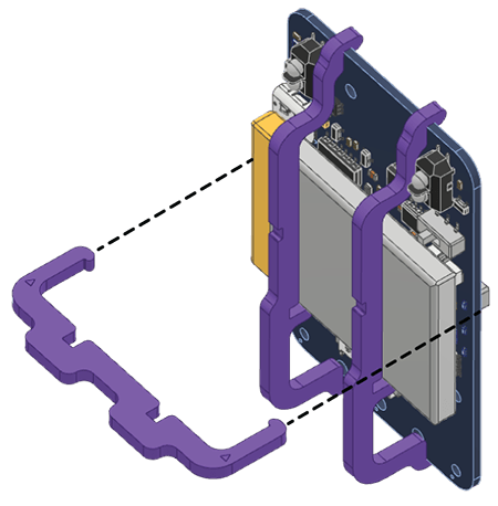
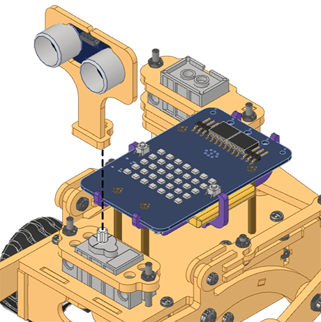
- First, connect the Battery by placing it on the backside of the Quarky. Keep the red wire towards the right side.
- Mount and snap the A1 Purple Parts to keep the Battery safe and secure.
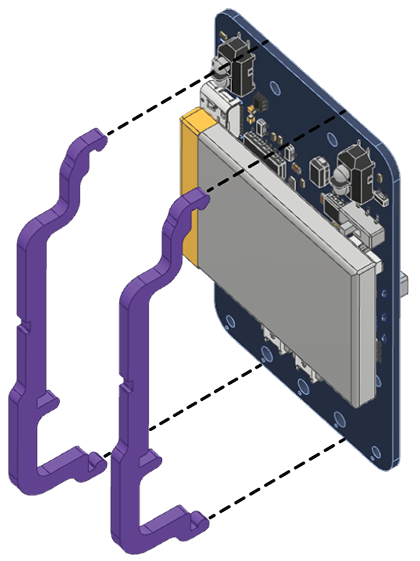
- Next, lock the A1 Purple Parts with the help of an A2 Purple Part. Press the parts gently to snap them.
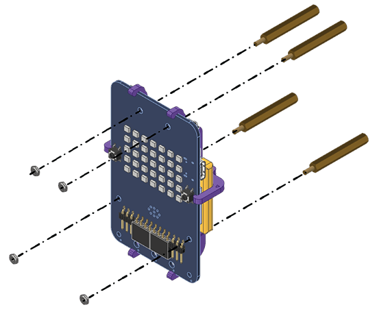
- Fix the M2 Metal Standoffs (30mm) to the back side of the Quarky and fix them with M2 Nuts.
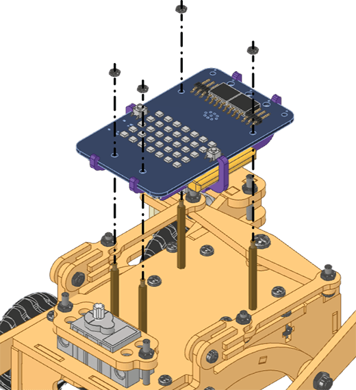
- Fix the assembled Quarky to the Body Top with M2 Bolts (6mm).
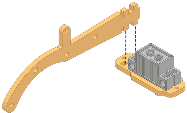
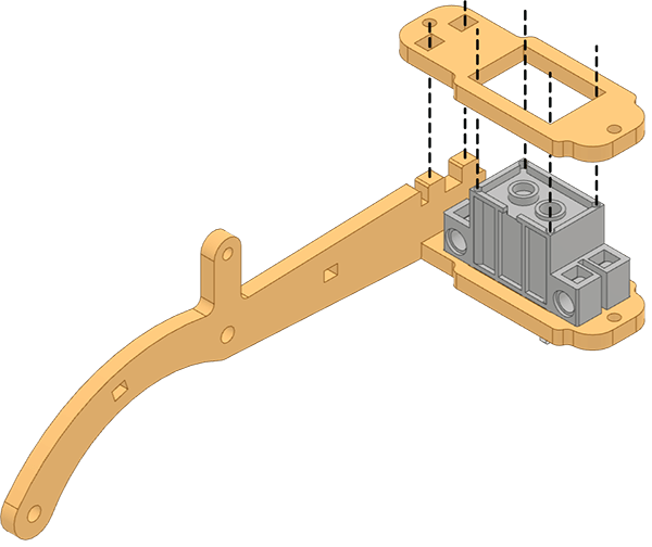
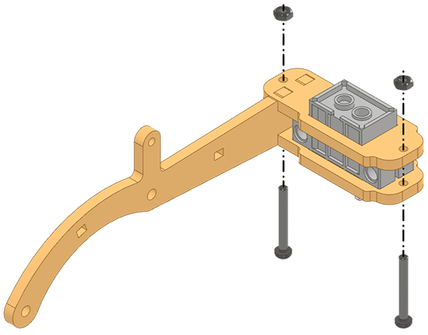
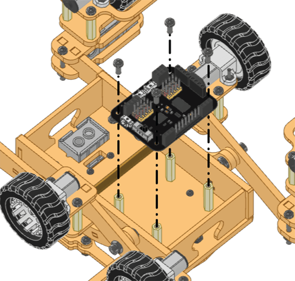
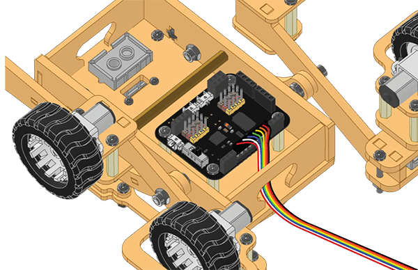
- Fix the Quarky Expansion Board on the bottom of the body using M3 Spacers (20mm). Secure the assembly with M3 Bolts (6mm).
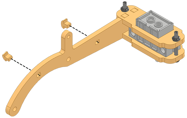
- Now attach the Expansion Connectors to the Quarky board as per wiring diagram 77.1.
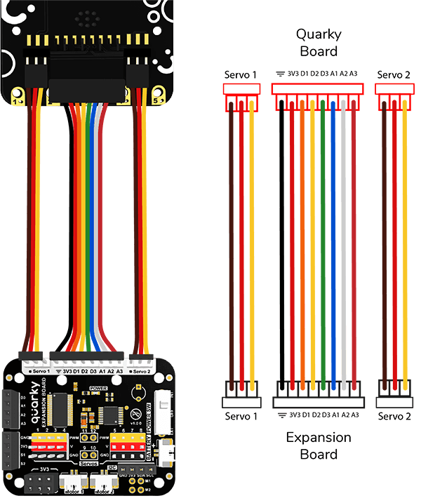
- Pass the Expansion Connectors from the wiring slot of the Body Short Side and connect them to the Quarky Expansion Board.
Complete:

HEAD ASSEMBLY
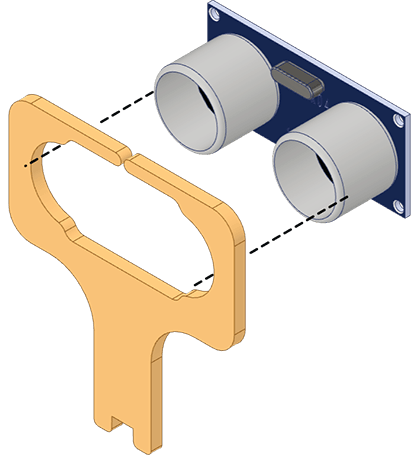
- Attach the Ultrasonic Holder to the Ultrasonic Coupling.

- Insert the Ultrasonic Sensor into the Ultrasonic Holder.
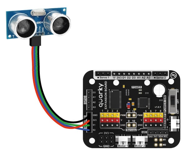
- Connect the Ultrasonic Connector to the Ultrasonic Sensor.
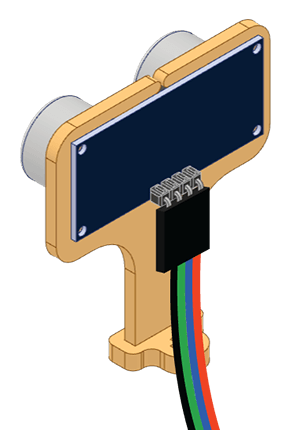 Wiring Diagram:

- Insert the Ultrasonic Coupling through the rectangular slot in the Body Top.
- Fix the Ultrasonic Base on 180° Servo Motor mounted on the Central Module.
- Connect the Ultrasonic Sensor to the Expansion board.
Wiring Diagram:
- Now follow Wiring diagram 85.1 to complete the servo connections.
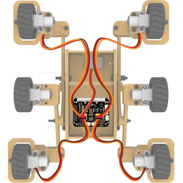
- Front Left Servo – Port 1
- Back Left Servo – Port 2
- Head Servo – Port 4
- Back Right Servo – Port 6

- Connect the two 3 Motor Junction Connectors to the Quarky Expansion Board and the Motors.
- Right Motors – Motor 2
- Left Motors – Motor 1

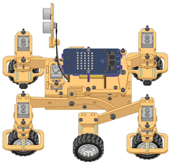
- The assembly is ready, and your Quarky Mars Rover is ready to roll.
Conclusion
In conclusion, we have gone through the steps of assembling the Quarky Mars Rover, from calibrating the servos to assembling the Left and Right Rocker Bogies, Differential Suspension Assembly, and Head Assembly. We have also gone through the wiring diagram to make all the appropriate connections. Following the steps in this lesson, you should now have a fully functional Quarky Mars Rover, ready to explore the world.