Introduction
In this tutorial, you will learn about the functioning of the relay and how to interface it with evive.
A relay is a switch that is operated through an electrical signal. There are different types of relays available some of them include electromagnetic relays, reed relays, contactors, solid-state relays, etc. They are mainly used in controlling high-power circuits with a low-power signal. For example, with the help of a relay, you can control an AC bulb with evive. You can control high-power AC as well as DC circuits with the relay. Relays have a wide range of applications in industries as well as in a large number of robotics-related projects.
Working of electromagnetic relays
A relay consists of an electromagnetic coil and a Single pole double throw switch (SPDT). An SPDT switch has one input and two outputs. As seen in the image there is a part in the symbol with marking NO, NC, and COM on it, that is an SPDT switch.
In this COM is the input of the switch, NC means normally closed and NO means normally open. Both NC and NO are outputs of the SPDT switch. The contact that connects the output to the input in SPDT is called the pole. The spring-like structure symbolizes an electromagnetic coil.
When the coil is not energized NC and COM remain connected in SPDT. As soon as the coil is energized NO and COM get connected. Actually, when the coil is energized magnetic field is generated around it, the pole gets attracted towards this field and it shifts itself from NC to NO. Hence NO and COM get connected. As soon as the coil gets de-energized coil losses its magnetic field and the pole moves back to its original position and NC and COM get connected again.

The coil is energized by supplying an electrical signal to it. Depending upon the types of signaling you can have relays like 5 V dc relays, 12 V dc relays, etc. You can use both 5V and 12V type relays with evive. 5V relay can be controlled by any digital pin and 12V relay can be controlled by motor terminals of evive. Through digital pin coil of the relay is given 5V which energizes it.
In this example, you will be controlling a 230V AC bulb with evive with the help of a 5V relay. The relay will be controlled by slide switch 1 on evive.
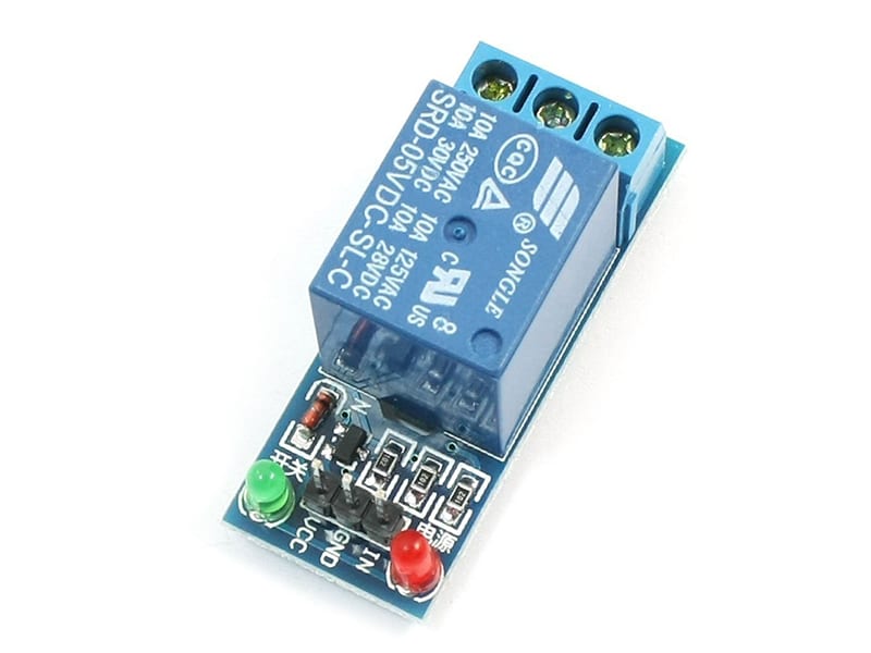
Specifications of relay
- 5V TTL control signal
- Maximum AC current and voltage: 10A 250VAC
- Maximum DC current and voltage: 10A 30VDC
- The 5V relay used in this example has 3 pins that are to be connected with evive. These pins are GND, VCC, and Signal.
- The module also has an onboard LED that glows whenever NO and COM get connected.
Circuit diagram
The image below shows the circuit diagram of the relay with evive for controlling an electrical bulb. Here VCC and GND of the relay are connected to 5V and GND of evive respectively and the Signal pin is connected to digital pin 2 on evive.
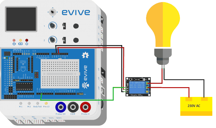
You can use the AC supply plug available n your home to power the bulb. Out of the two wires plugged in a plug connect one to the COM of the relay and one directly to the bulb holder.

PictoBlox Program
Follow the steps:
- Open PictoBlox.
- Select the board as evive:
- Connect the evive.
- Create the following script using when evive starts up block:
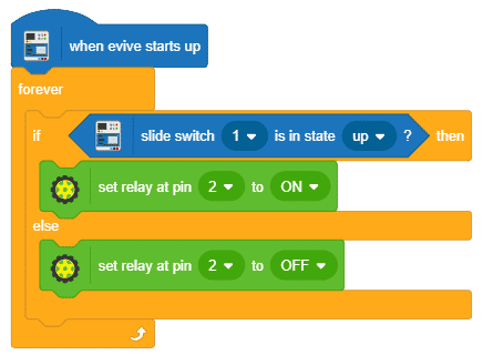
- Upload the code onto evive:
You can download the PictoBlox program from here: Interfacing Relay with evive
Output
Conclusion
In conclusion, this tutorial has provided an overview of the functioning of the relay and how to interface it with evive. It has covered the working of an electromagnetic relay, its specifications, the circuit diagram, and the PictoBlox program. The output of this tutorial is a working circuit for controlling an electrical bulb with evive. With the help of this tutorial, you can now easily interface relays with evive to control high-power circuits with a low-power signal.