
Introduction
Quarky Intellio Rover is a programmable robot that is built using Quarky Intellio, an ESP32-S3-based AI and AR module with an inbuilt camera, microphone, speaker, and battery. The rover uses construction parts, DC motors, and a servo to enable autonomous movement, vision-based detection, and interactive behaviors. It supports Block coding and Python, making it suitable for learning robotics, edge AI, and computer vision applications, including integrations with tools and libraries such as OpenCV, etc., for advanced vision-based projects in makerspaces and classrooms.
Please follow the steps given below to construct the Quarky Intellio Rover.
You can also refer to the YouTube video “Quarky Intellio Rover Assembly Guide” for a step-by-step visual explanation.
To purchase the Quarky Intellio Rover Kit and begin your robotics journey, visit the link: Explore the Quarky Intellio Rover Kit.
Note:
- In each step, refer to the image for the exact orientation, alignment, and hole positions. The box in the top-right corner of each image shows the parts required for that step.
- In the instruction steps, the images in the top-right corner show the parts used for the corresponding assembly step.
Supplies
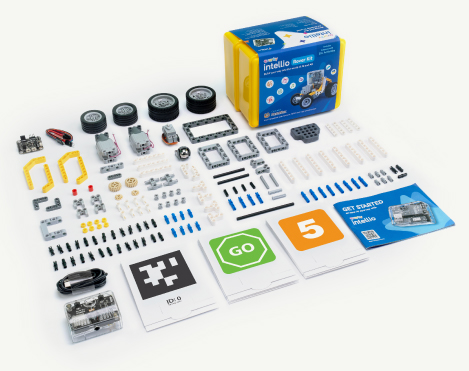
Box 1:
- 1x Quarky Intellio
- 1x USB-C Cable
- 1x Set of AR Markers
- 1x Set of Recognition Markers
- 1x Set of Construction Parts
- 1x Getting Started Guide (Instruction Manual)
Box 2:
- 1x Quarky Mini Expansion Board
- 1x Mini Expansion Connector
- 1x 180° Servo Motor
- 2x Motors
- 2x Set of Wheels
- 1x Set of Axles and Gears
- 1x Set of Construction Parts
PictoBlox Software download here: https://thestempedia.com/product/pictoblox/download-pictoblox/

Helpful Tip Before You Start
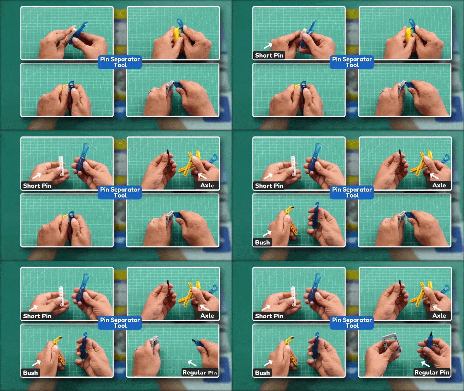
Some connector pins may fit tightly and can be difficult to remove by hand. Use the Pin Separator Tool to remove them safely without damaging the construction parts.
Refer to the Pin Separator Tool demonstration before beginning the assembly.
Step-by-Step Assembly Instructions
Step 1: Prepare the Main Motor
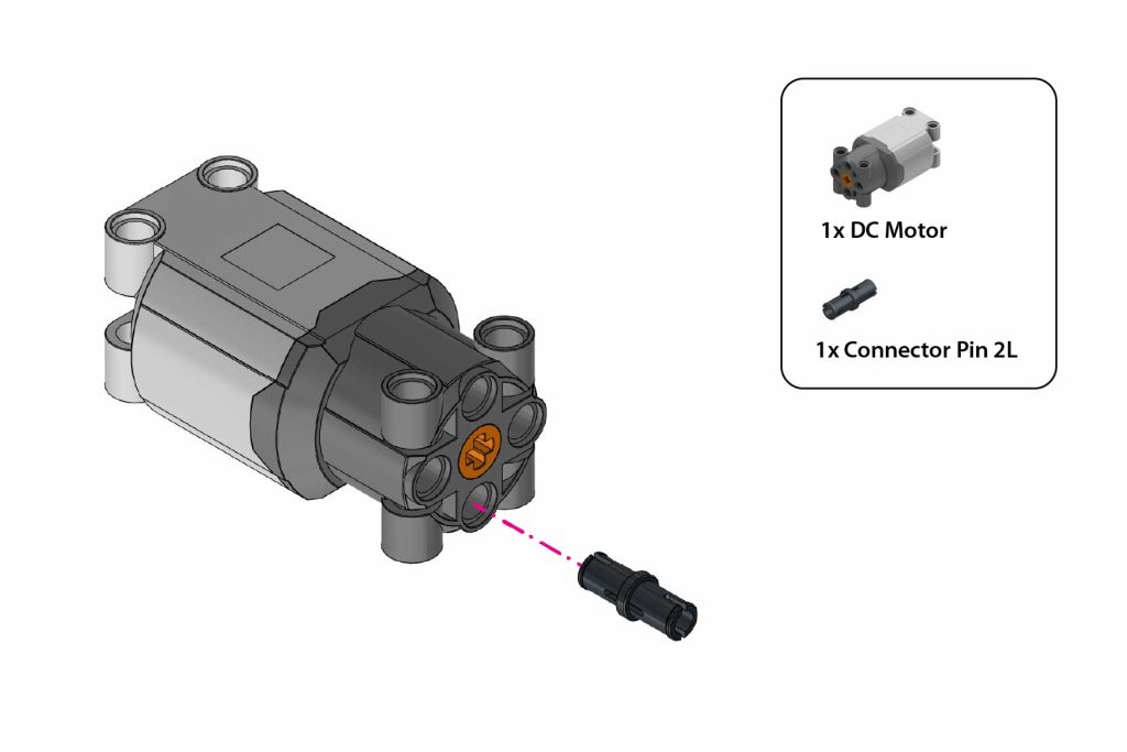
- Identify 1x DC Motor and 1x Connector Pin 2L.
- Insert Connector Pin 2L into the bottom-most front hole of the DC Motor.
Step 2: Mount the Motor on the Main Frame
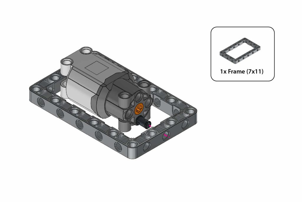
- Align the centre hole of the Frame (7×11) with the pin attached to the motor.
- Press the Frame (7×11) onto the pin until the motor is fixed at the centre.
Step 3: Attach Frame Structure
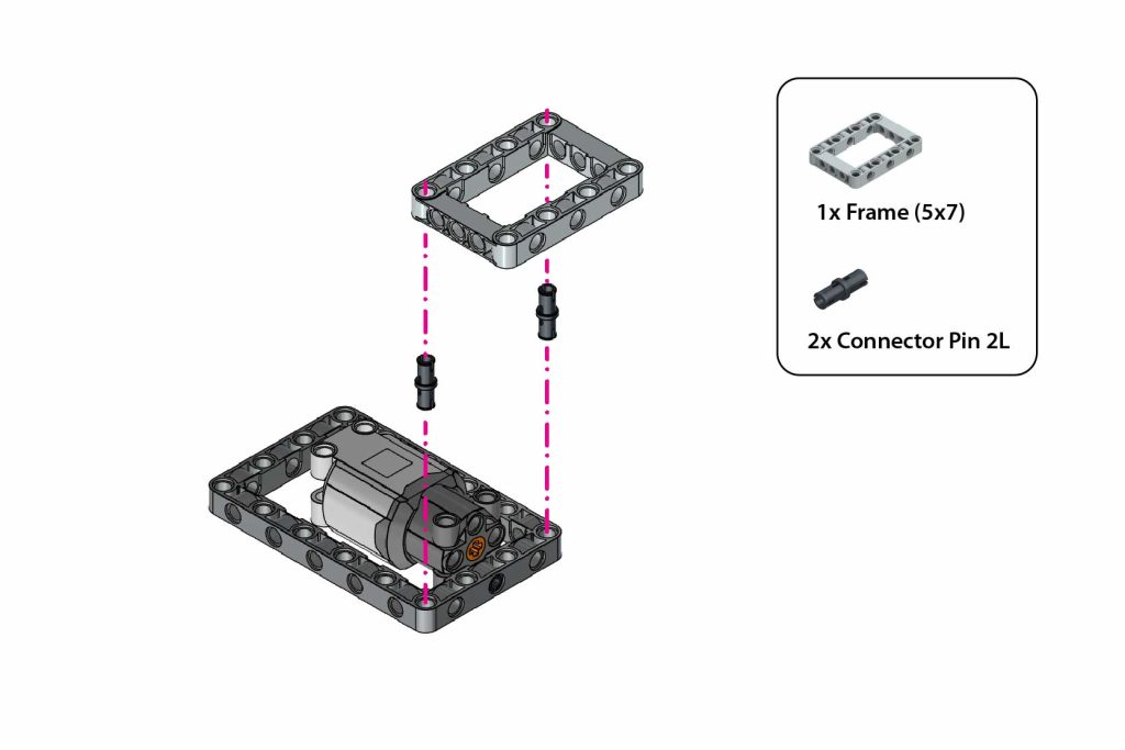
- Insert 2x Connector Pin 2L into the two corner holes of the Frame (7×11).
- Place the Frame (5×7) over the pins.
- Press the Frame (5×7) down to attach it firmly to the Frame (7×11).
Step 4: Insert Gear Assembly
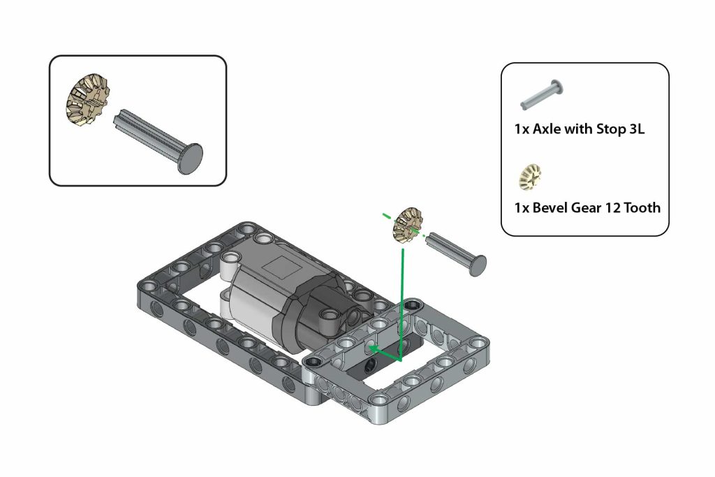
- Slide the Bevel Gear 12 Tooth onto the Axle with Stop 3L, with the teeth facing the stop end.
- Insert the axle assembly through the side hole of the Frame (5×7) and into the motor.
Step 5: Add T-Shape Beam
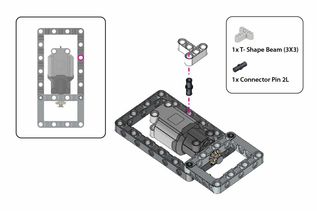
- Insert 1x Connector Pin 2L into the top-right hole near the motor.
- Attach 1x T-Shape Beam (3×3) onto the pin as shown.
After attaching, rotate the T-Shape Beam towards the motor so that it aligns with the motor as shown in the image.
Step 6: Repeat Left Side Assembly
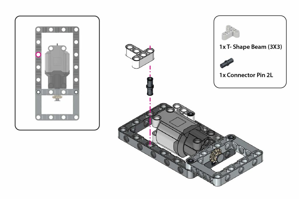
- Insert 1x Connector Pin 2L into the top-left hole near the motor.
- Attach the second T-Shape Beam (3×3) onto the pin horizontally.
After attaching, rotate the T-Shape Beam towards the motor so that it aligns with the motor as shown in the image.
Step 7: Secure Motor With Pins
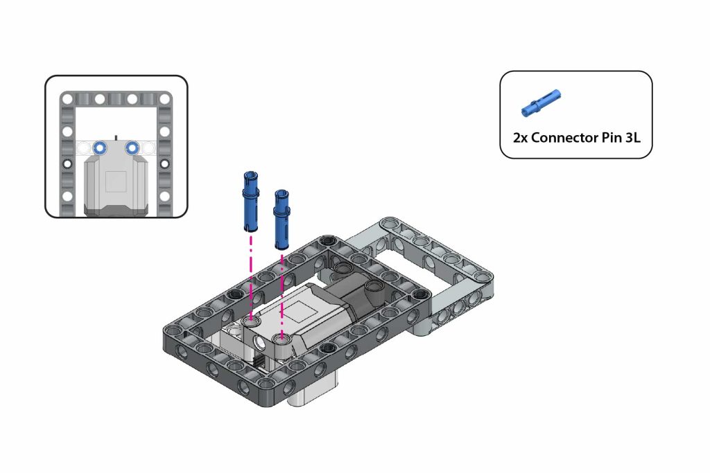
Turn the assembly upside down so that the Frame (7×11) is on top and the Frame (5×7) is at the bottom, as shown in the image.
Then insert 2x Connector Pin 3L into the two highlighted holes on the top side.
Step 8: Insert Axle Through Frame
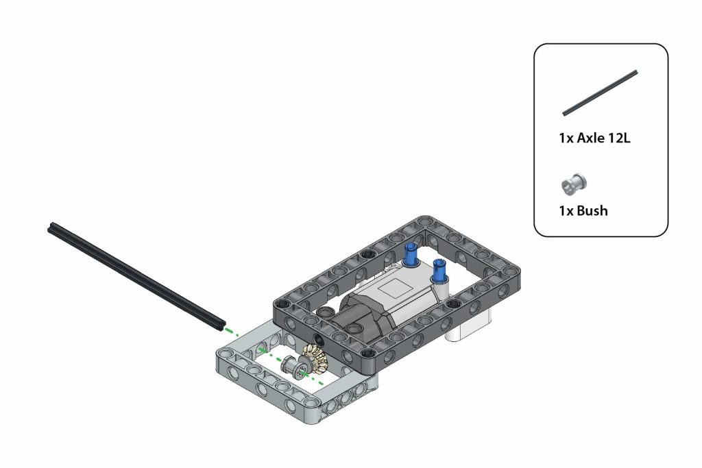
- Insert 1x Axle 12L through the side holes of the Frame (5×7) and the motor assembly.
- Attach 1x Bush onto the exposed axle end to secure it in place.
Step 9: Add Bevel Gear
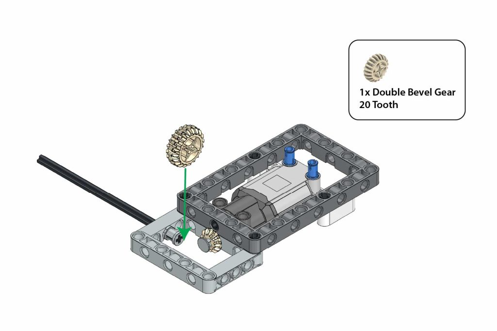
Slide 1x Double Bevel Gear 20 Tooth onto the Axle 12L and align it with the Bevel Gear 12 Tooth.
Step 10: Complete Axle Assembly
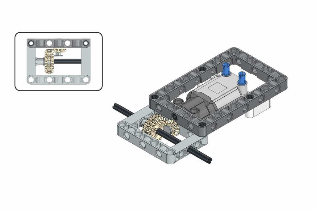
- Push the Axle 12L fully through the frame until it comes out from both sides.
- Make sure the Double Bevel Gear 20 Tooth meshes properly with the Bevel Gear 12 Tooth.
Step 11: Prepare Servo Motor
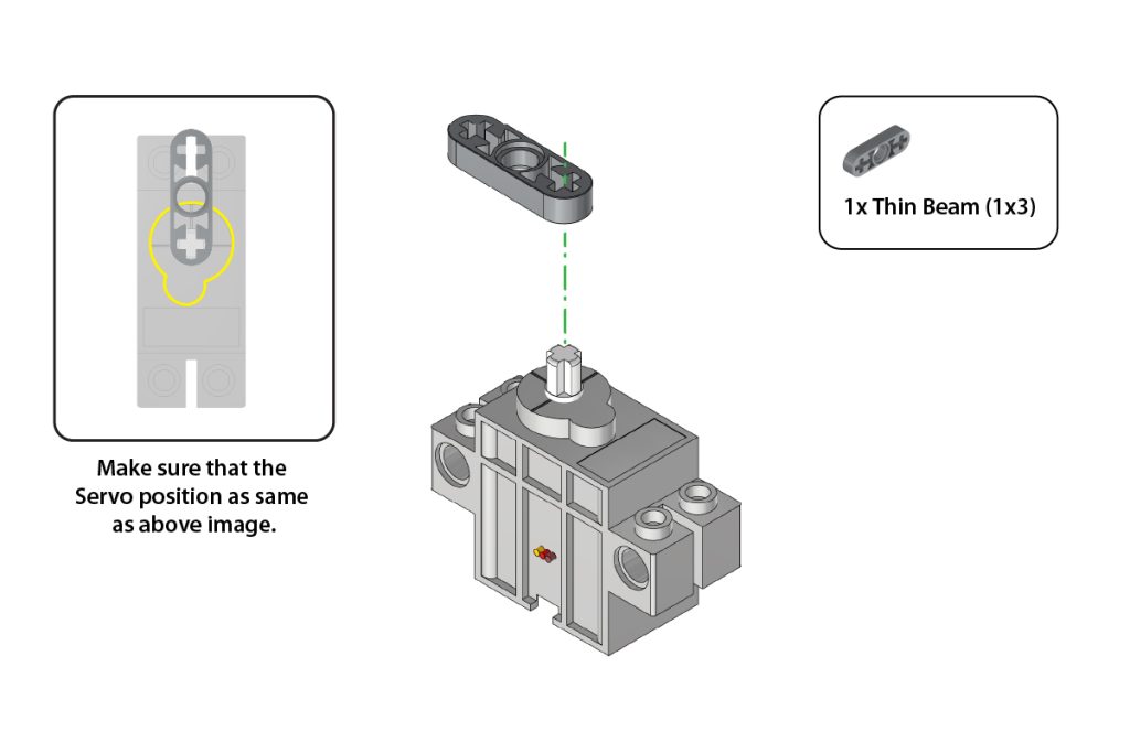
Step 12: Fix Pins on Servo
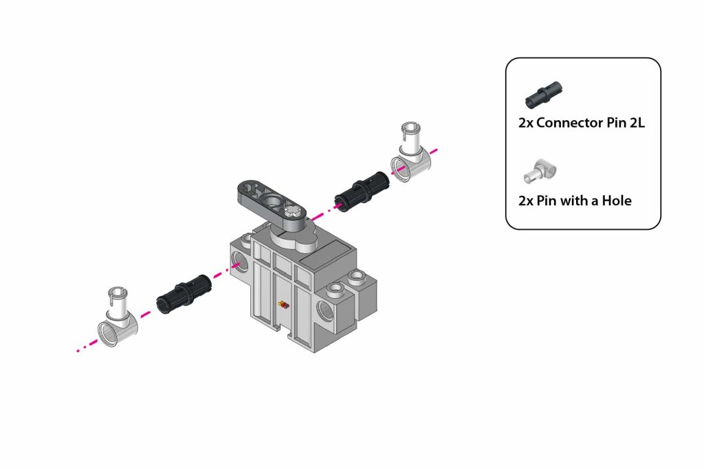
- Insert 2x Connector Pin 2L into the side holes of the motor. Attach 2x Pin with a Hole onto the exposed ends of the pins, facing outward.
Step 13: Verify Servo Assembly
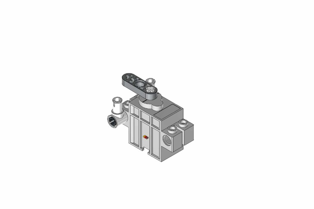
Step 14: Add Connectors to Servo
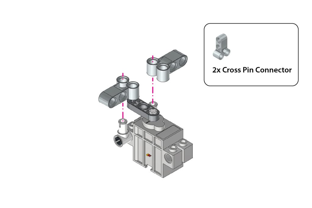
Attach 2x Cross Pin Connector to the top pins of the Cross Pin Connector facing outward, as shown.
Step 15: Insert Split Connectors
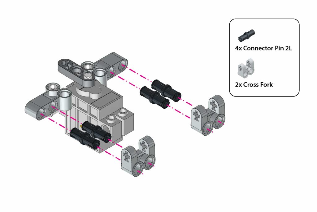
- Insert 4x Connector Pin 2L into the holes of the Cross Pin Connector.
- Attach the 2x Cross Fork onto the connector pins.
- Press both Cross Fork pieces firmly so they face outward on both sides.
Step 16: Mount L-Shape Beam (Right)
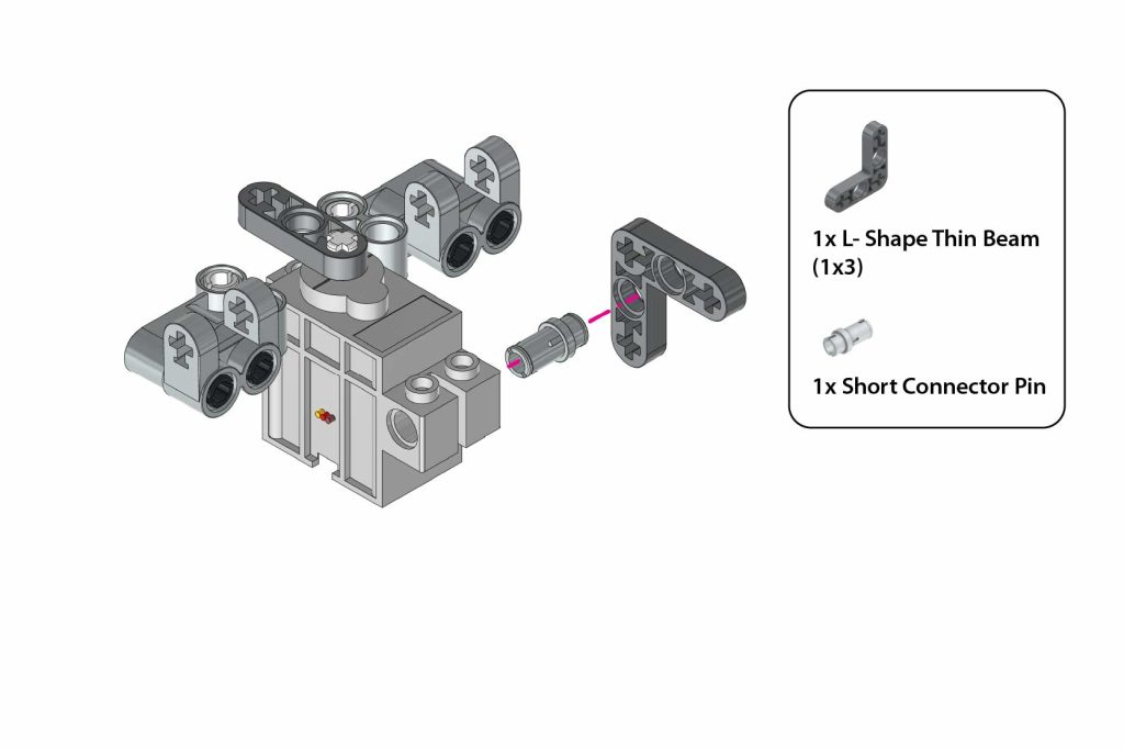
- Insert 1x Short Connector Pin into the remaining lower side hole of the motor.
- Attach 1x L-Shape Thin Beam (1×3) onto the pin, facing outward as shown.
Step 17: Mount L-Shape Beam (Left)
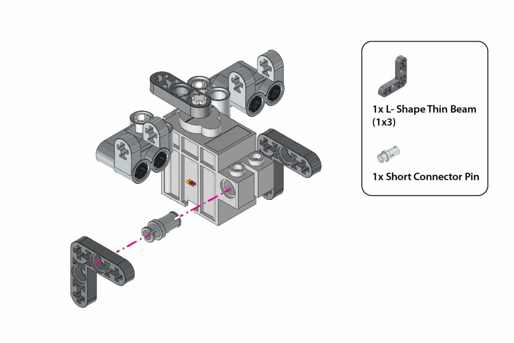
Repeat the same on the other side of the 180° Servo Motor as illustrated.
Step 18: Insert Axle Through Beams
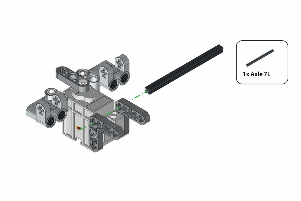
Step 19: Secure Axle (Right Side)
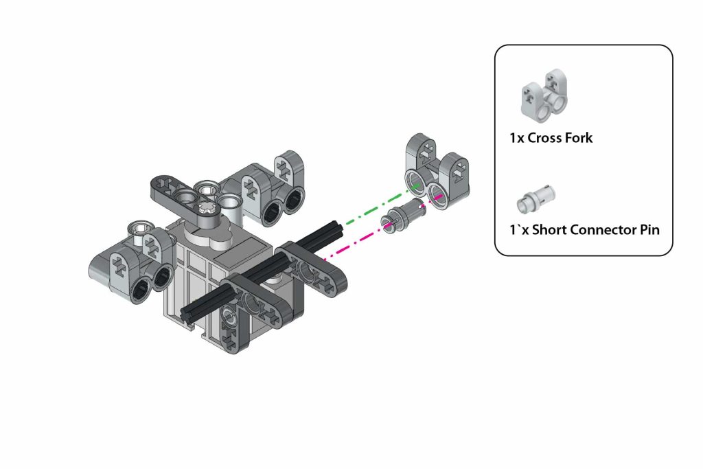
- Insert 1x Short Connector Pin into the side hole of the Cross Fork.
- Attach 1x Cross Fork to the exposed end of the Axle 7L and L-Shape Thin Beam (1×3).
Step 20: Secure Axle (Left Side)
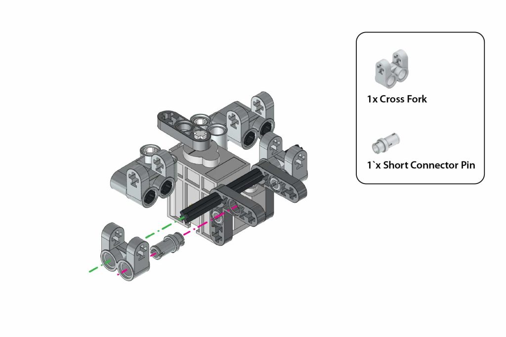
Repeat on the other Side.
Step 21: Add Bushes to Axle
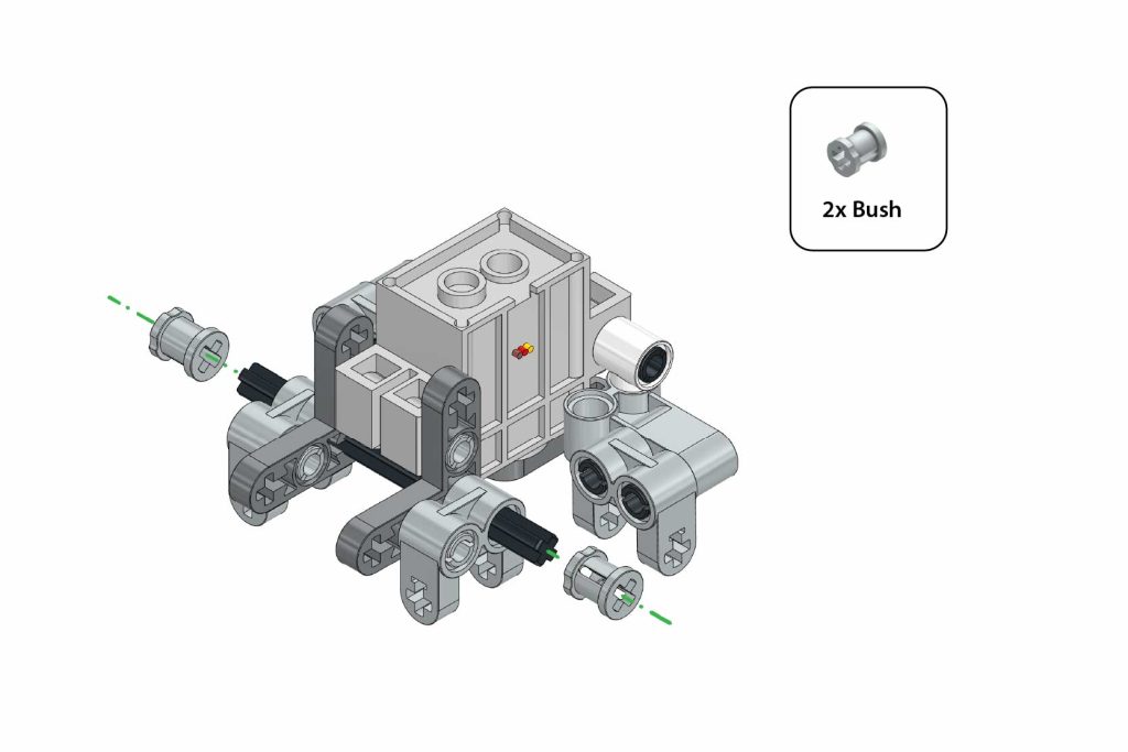
Attach 2x Bush onto both exposed ends of the Axle 7L to lock the assembly in place.
Step 22: Attach Cross Beam
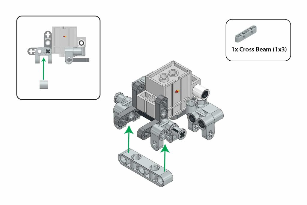
Attach 1x Cross Beam (1×3) to the central holes in the Cross Fork of the motor assembly as illustrated.
Step 23: Secure Beam With Axles
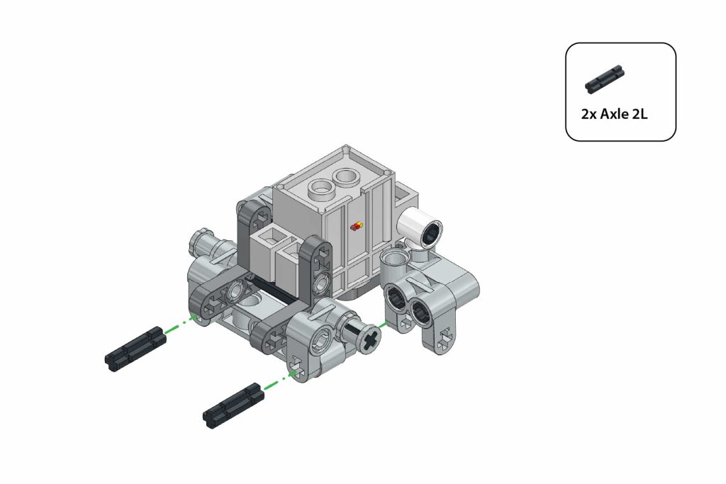
Insert 2x Axle 2L through the side holes of the Cross Fork to secure the Cross Beam (1×3).
Step 24: Attach Servo to Main Assembly
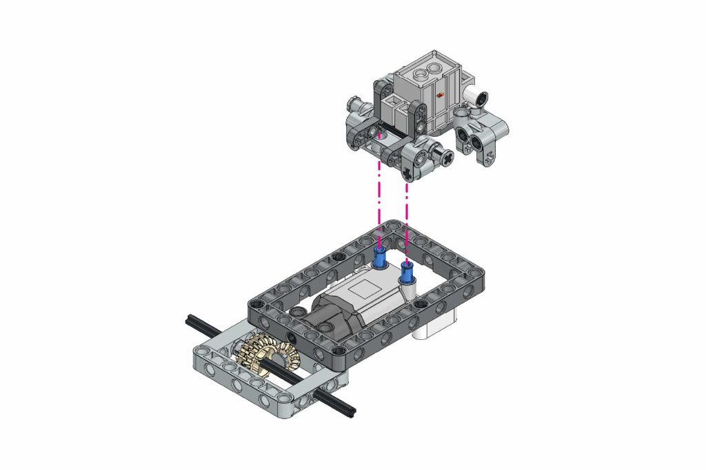
- Align the motor assembly with Connector Pin 3L on the Cross Beam (1×3) as shown in the figure.
Step 25: Attach Bent Beam (Left)
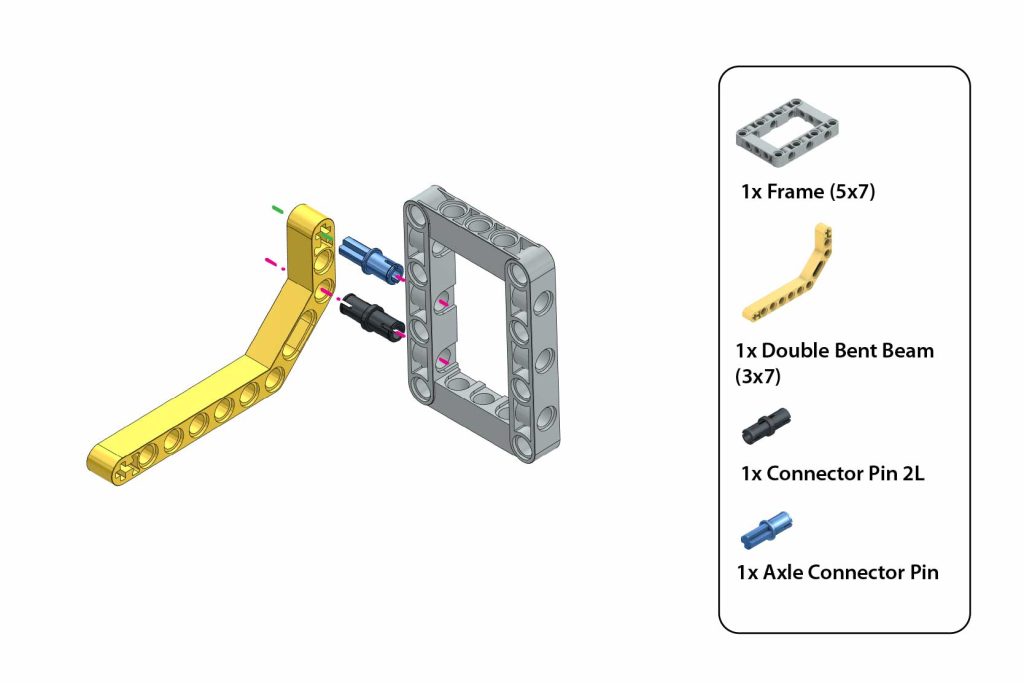
- Attach the 1x Double Bent Beam (3×7) to the Frame (5×7) using 1x Connector Pin 2L and 1x Axle Connector Pin, as shown in the figure.
Step 26: Attach Bent Beam (Right)
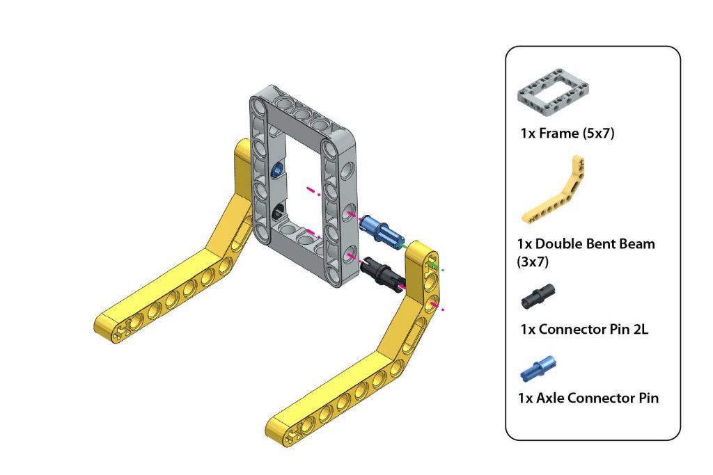
Repeat the same on the other side using the same components, as shown in the figure.
Step 27: Verify Sub-Assembly
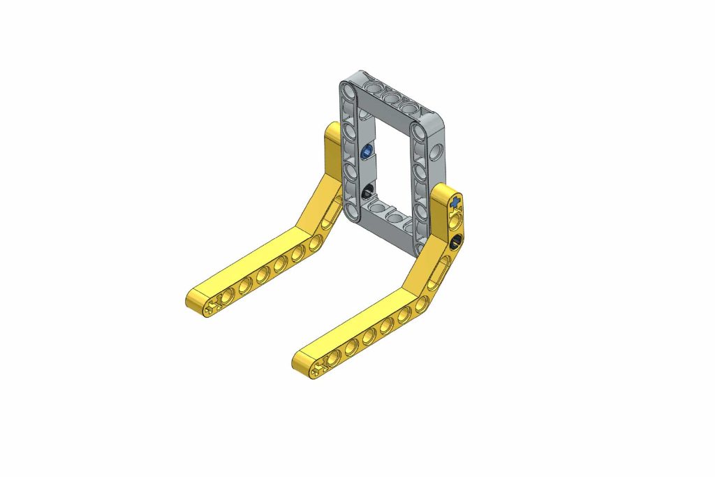 The base frame is ready for the next steps in assembly.
Step 28: Mount Sub-Assembly
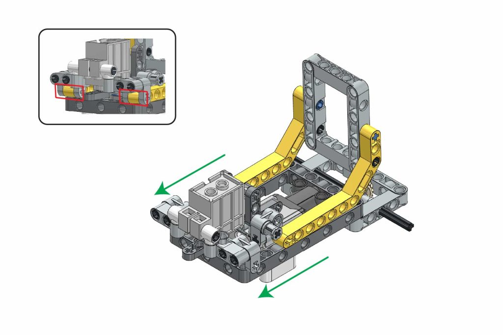
Ensure the motor assembly is securely attached to the Double Bent Beam by connecting it to the Cross Fork at the marked locations, as shown in the figure.
Step 29: Secure Sub-Assembly
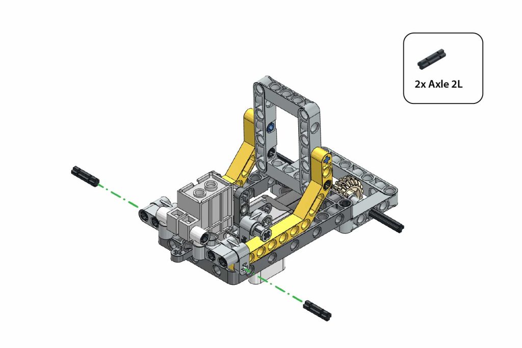
Insert 2x Axle 2L through the holes on both sides of the Cross Fork to secure the structure in place.
Step 30: Attach Beam and Connectors
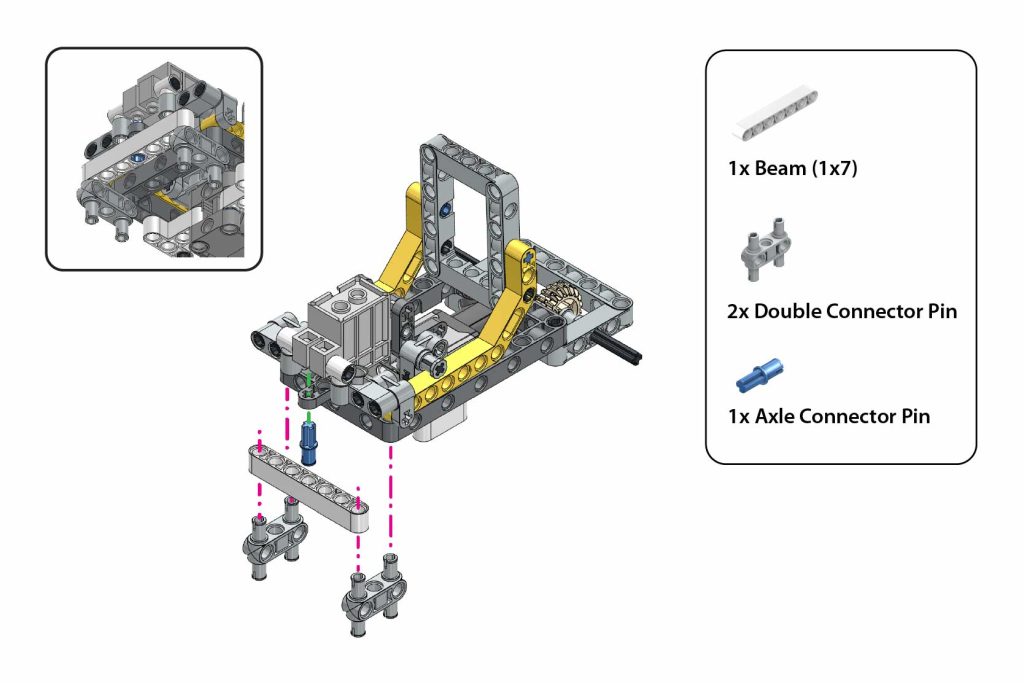
- Attach 1x Beam (1×7) to the structure using 2x Double Connector Pin.
- Secure the Beam (1×7) by inserting 1x Axle Connector Pin through the hole of the Thin Beam of the Servo Motor, and the Beam (1×7) as shown in the figure.
Step 31: Mount L-Shape Beam (Right Side)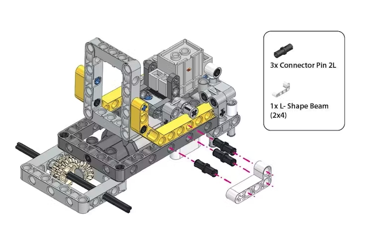
- Insert 3x Connector Pin 2L into the marked holes of the Frame (7×11) and Double Bent Beam (3×7) assembly, as shown in the figure.
- Attach 1x L-Shape Beam (2×4) to the structure using 1x Connector Pin 2L for secure fitting.
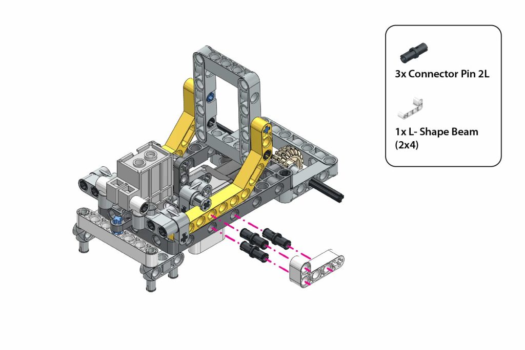
Step 32: Mount L-Shape Beam (Left Side)
Step 33: Install Right Wheel
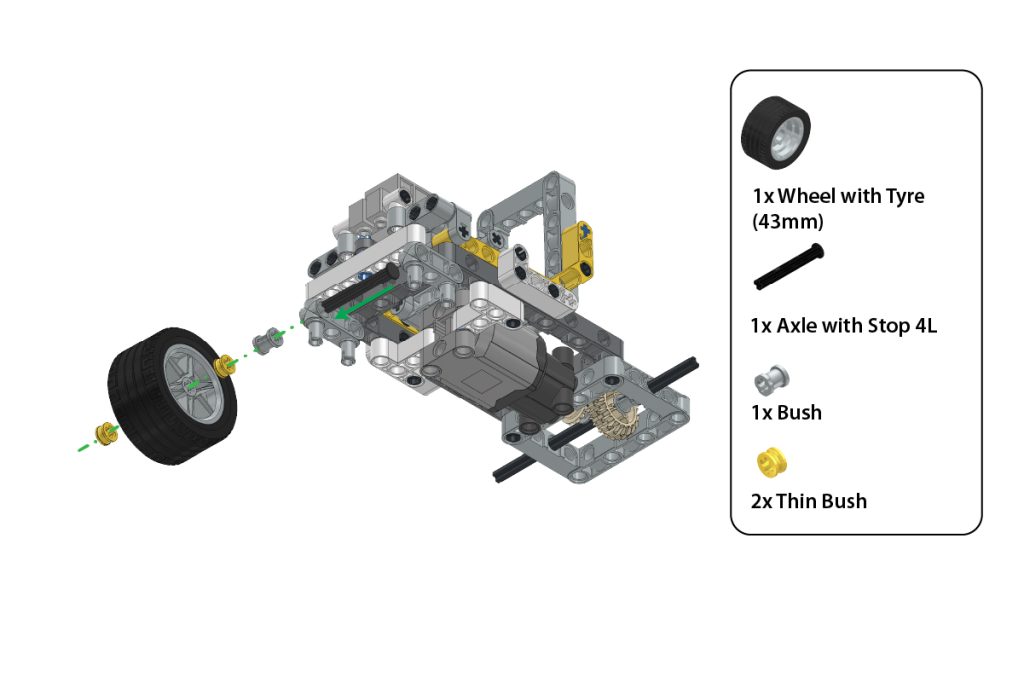
- Slide 1x Axle with Stop 4L through the assembly.
- Attach 1x Wheel with Tyre (43mm) onto the axle.
- Secure the wheel by adding 1x Bush and 2x Thin Bush on either side of the wheel.
Step 34: Install Left Wheel
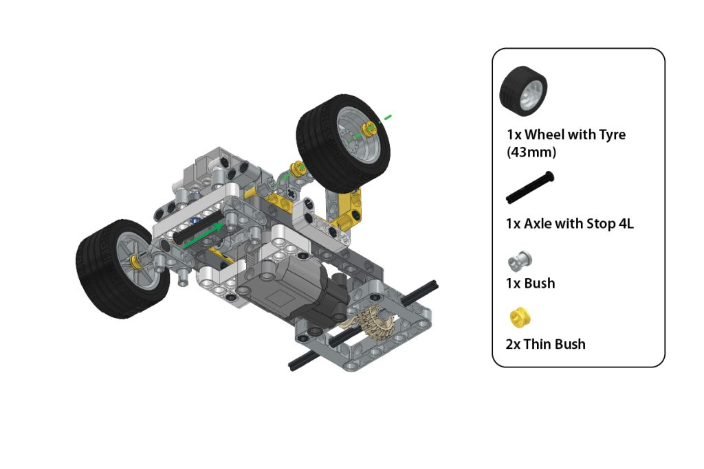
- Insert 1x Axle with Stop 4L through the assembly for the second set of wheels.
- Attach 1x Wheel with Tyre (43mm) onto the axle.
- Secure the wheel with 1x Bush and 2x Thin Bush on each side of the wheel.
Step 35: Attach Rear Frame
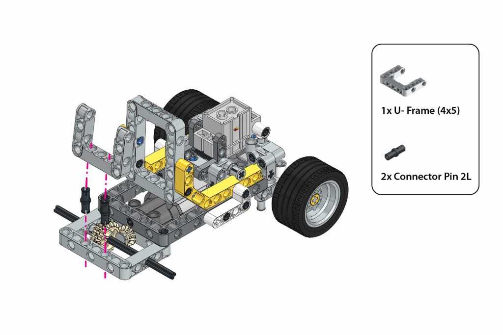
Secure the 1x U-Frame (4×5) to the Frame (5×7) using 2x Connector Pin 2L, ensuring proper alignment as shown in the image.
Step 36: Attach the Bent Beam
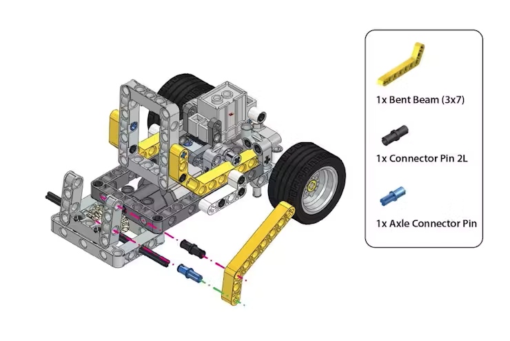
Step 37: Add the Beam
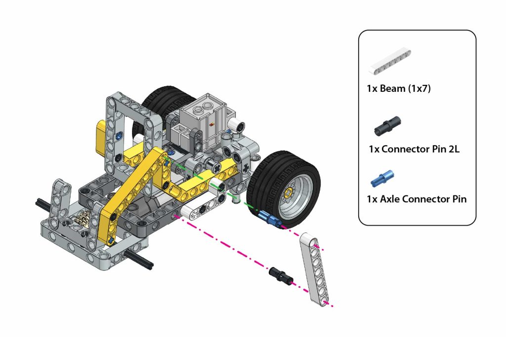
Connect 1x Beam (1×7) to the existing structure using 1x Connector Pin 2L and 1x Axle Connector Pin, ensuring proper alignment as shown in the image.
Step 38: Attach Bent Beam
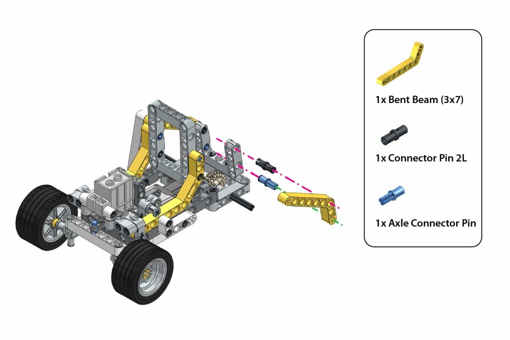
Attach the 1x Bent Beam (3×7) using 1x Connector Pin 2L and 1x Axle Connector Pin to complete the structure as shown in the image.
Step 39: Add the Beam.
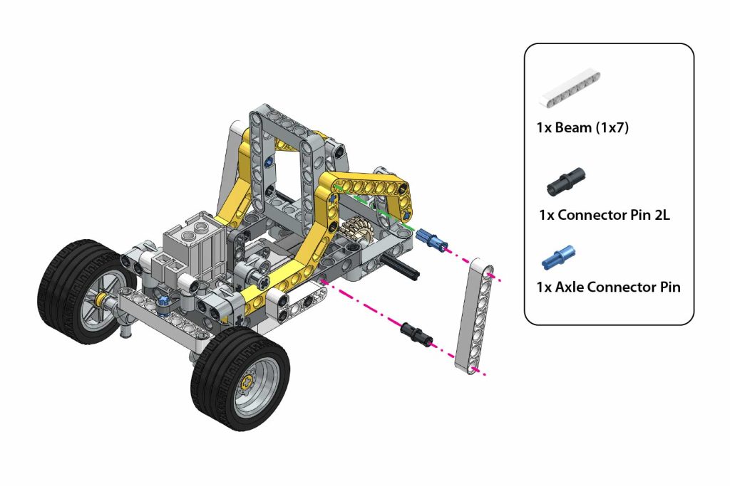
Step 40: Install Rear Wheels
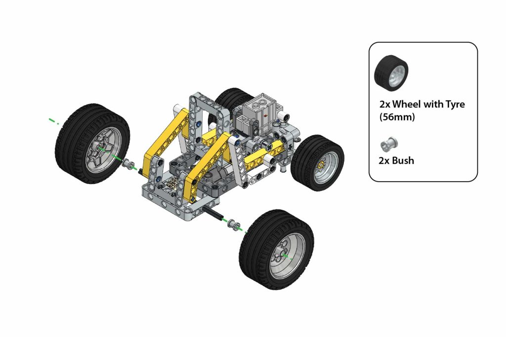
Attach the 2x Wheels with Tyre (56mm) and 2x Bush to the axles as shown in the image.
Step 41: Attach Expansion Board.
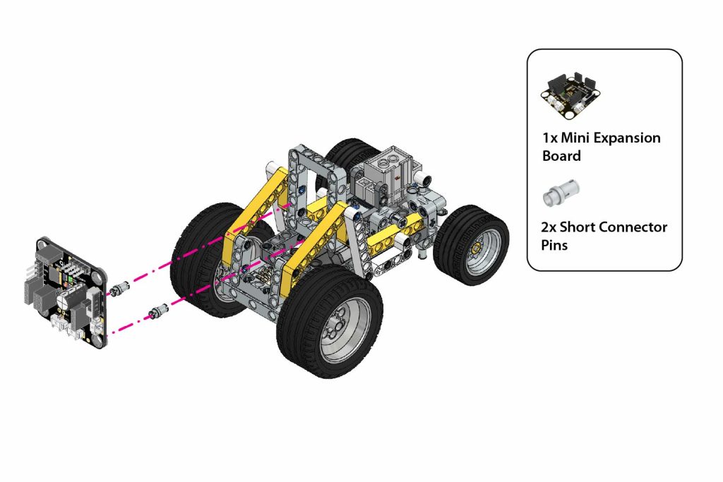 Secure the Mini Expansion Board using 2x Short Connector Pins, ensuring a stable connection.
Step 42: Attach the Intellio Module
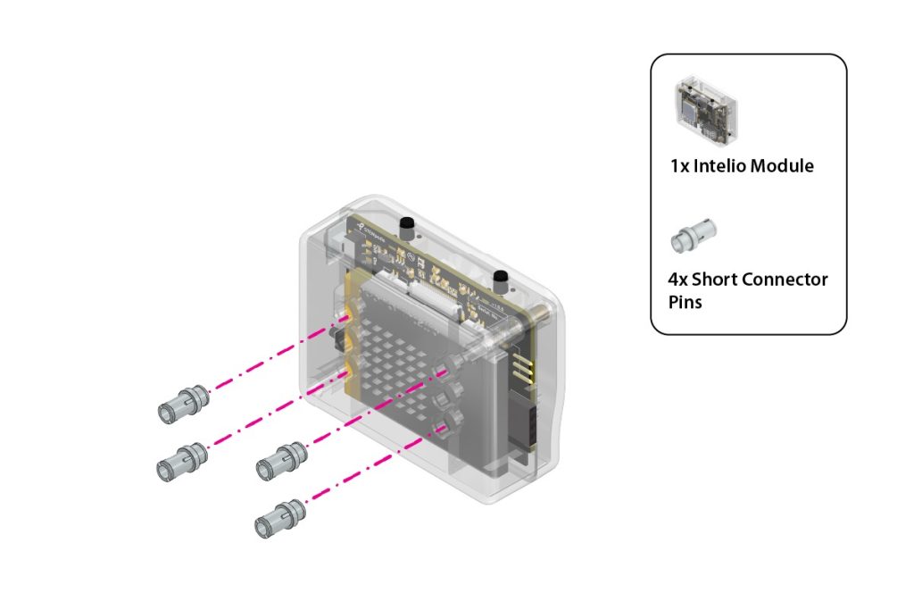
Attach the Intellio Module to the enclosure using 4x Short Connector Pins as shown in the image.
Step 44: Mount Intellio Device
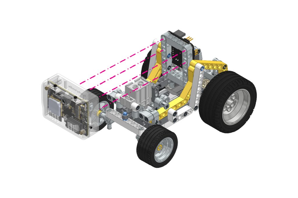
Attach the Intellio Module to the robot frame as shown, securing it in place using the previously added structure.
Step 45: Check Assembly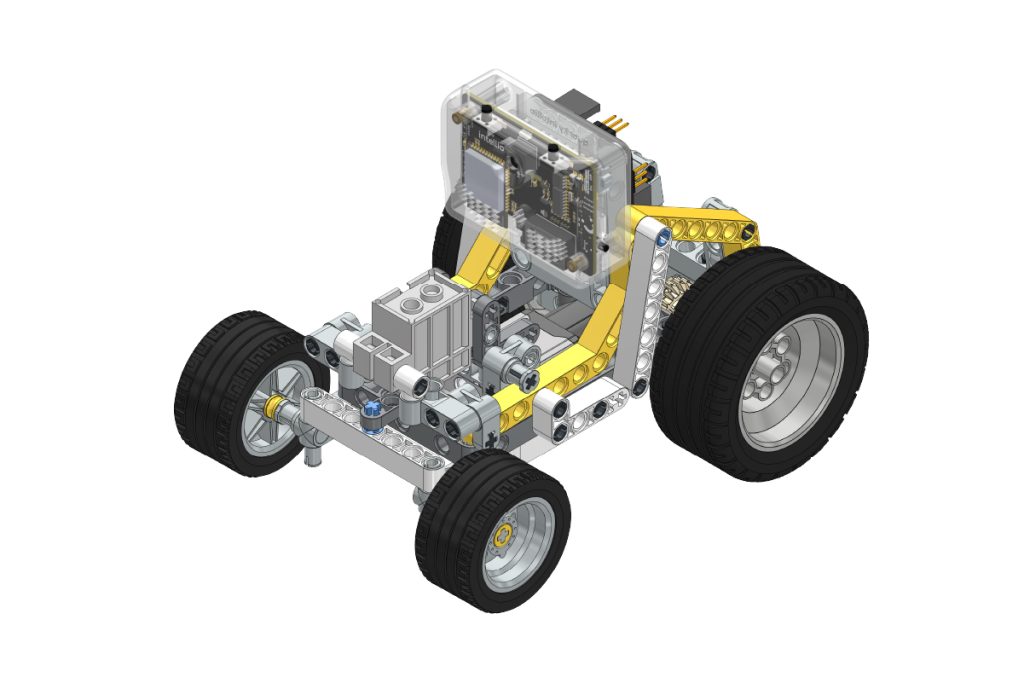
After completing the previous step, the assembly should look as shown.
Step 46: Connect Wiring
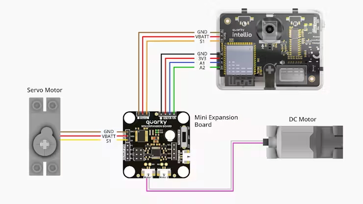
Connect the Mini Expansion Connectors and Motor Connection on the Mini Expansion Board and Quarky Intellio as per the wiring diagram.
Step 47: Complete Rover Assembly
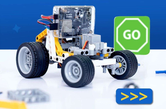
The assembly of Quarky Intellio Rover is now complete.
Connect Intellio to PictoBlox
Step 1: Open PictoBlox, create a new project in block mode, click on Board, and select Quarky Intellio.
Step 2: Connect Intellio to PictoBlox. Follow the step-by-step instructions in the Quarky Intellio Connection Guide to establish the connection.

Step 3: If you face any issues while connecting Quarky Intellio, refer to the troubleshooting guide below: Quarky Intellio Connections Guide Troubleshooting. Add the required extension: Quarky Mini Expansion Board.
Step 4: Initialize Rover Program
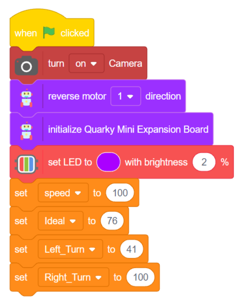
Create the following script to initialize the Rover when the flag is clicked.
Step 5: Add Keyboard Controls for Rover
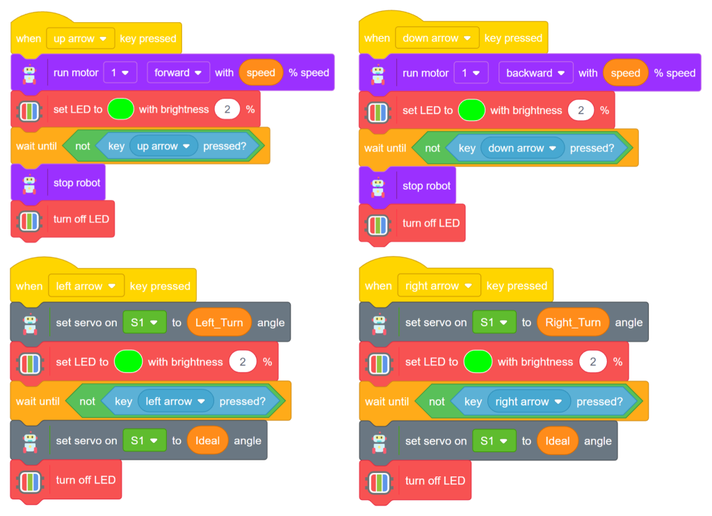
For the Up, Down, Left, Right Arrow Keys, code the blocks provided in image a.
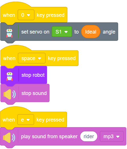
For the “0” “space” “e” Keys on the Keyboard, use the script as shown in image b.
Explore the Quarky Intellio Rover Kit
The Rover can be extended beyond keyboard control to build projects involving:
- Object detection
- Face and gesture recognition
- Camera-based navigation
- OpenCV applications
- Voice-controlled movement
- Autonomous obstacle avoidance
- Interactive AI behaviours
- Augmented-reality activities
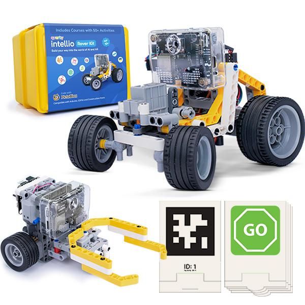
Explore the endless possibilities with the Quarky Intellio Rover Kit. Discover more about the kit and exciting project ideas built using Intellio.
To purchase the Quarky Intellio Rover Kit and begin your robotics journey, explore the Quarky Intellio Rover Kit and start building intelligent robotics and computer-vision projects today.