
Introduction
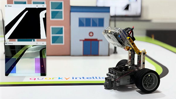
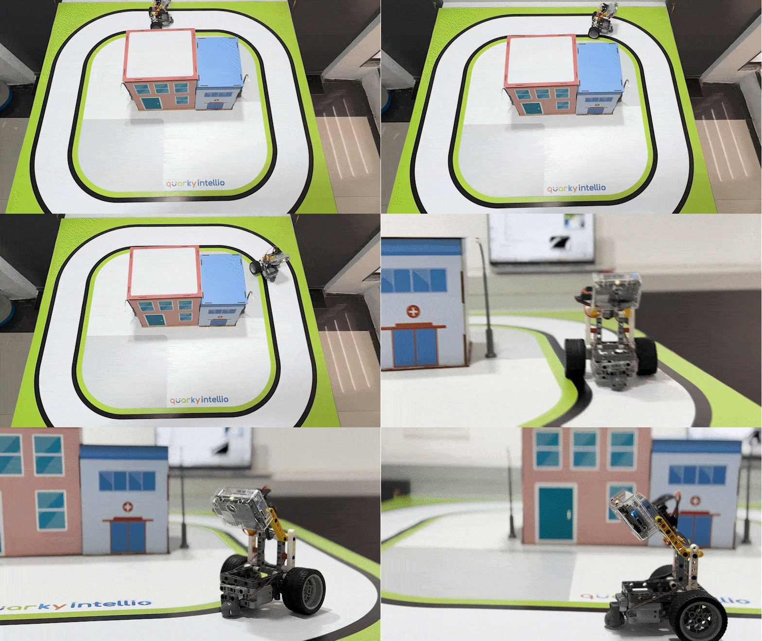
The Quarky Intellio Lane Follower Robot is a functional robotic model designed to demonstrate autonomous navigation using camera-based lane detection, OpenCV image processing, and motor-controlled movement.
For users familiar with the ESP32-CAM, Quarky Intellio works similarly to an ESP32-CAM for lane-following projects, as its built-in camera provides a live video feed that can be processed using OpenCV in Python. Instead of requiring a separate ESP32-CAM module, Quarky Intellio combines camera-based vision with robotics capabilities, allowing the program to detect the lane, determine the robot’s position, and control its motors accordingly.
Unlike basic line follower robots that rely only on IR sensors, this project processes the live camera feed to identify the lane and continuously correct the robot’s movement.
This project is useful for learning ESP32-CAM-style lane following, camera-based lane following, OpenCV lane detection, computer vision, Python robotics, image processing, motor control, and autonomous navigation.
To purchase the Quarky Intellio Rover Kit and begin your robotics journey, visit the link: Explore the Quarky Intellio Rover Kit.
Please follow the step-by-step instructions below to construct the Quarky Intellio Lane Follower Robot.
Helpful Tip Before You Start
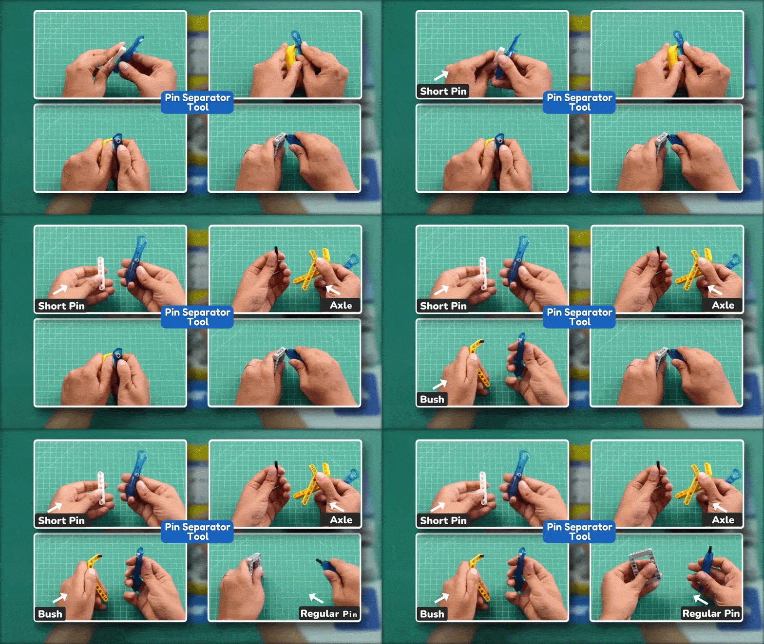
During assembly, some small connector pins may fit tightly and can be difficult to remove by hand. In such cases, use the Pin Separator Tool to remove the pin easily and safely. Refer to the GIF below to understand how to use the tool correctly before starting the assembly.
Note:
- In each step, refer to the image for the exact orientation, alignment, and hole positions. The box in the top-right corner of each image shows the parts required for that step.
- In the instruction steps, the images in the top-right corner show the parts used for the corresponding assembly step.
Supplies
Box 1:
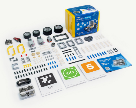
- 1x Quarky Intellio
- 1x USB-C Cable
- 1x Set of AR Markers
- 1x Set of Recognition Markers
- 1x Set of Construction Parts
- 1x Getting Started Guide (Instruction Manual)
Box 2:
- 1x Quarky Mini Expansion Board
- 1x Mini Expansion Connector
- 1x 180° Servo Motor
- 2x Motors
- 2x Set of Wheels
- 1x Set of Axles and Gears
- 1x Set of Construction Parts
PictoBlox Software: Download here: https://thestempedia.com/product/pictoblox/download-pictoblox/
Step-by-Step Assembly Instructions
Step 1: Prepare the First Motor Sub-Assembly
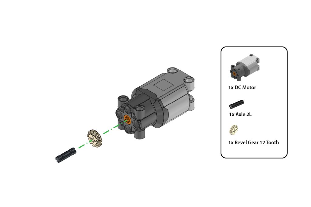
Take:
- one (1) DC Motor
- one (1) Axle 2L
- one (1) Bevel Gear 12 Tooth
Insert the Axle 2L into the shaft of the DC Motor. Attach the Bevel Gear 12 Tooth to the exposed end of the axle.
Press the gear firmly until it is securely fitted and aligned straight with the motor shaft, as shown in the image.
Step 2: Prepare the Second Motor Sub-Assembly
Repeat Step 1 to create a second identical motor sub-assembly.
Ensure both motor sub-assemblies have the same orientation and that both gears are fitted securely.
Step 3: Verify the Motor Sub-Assemblies
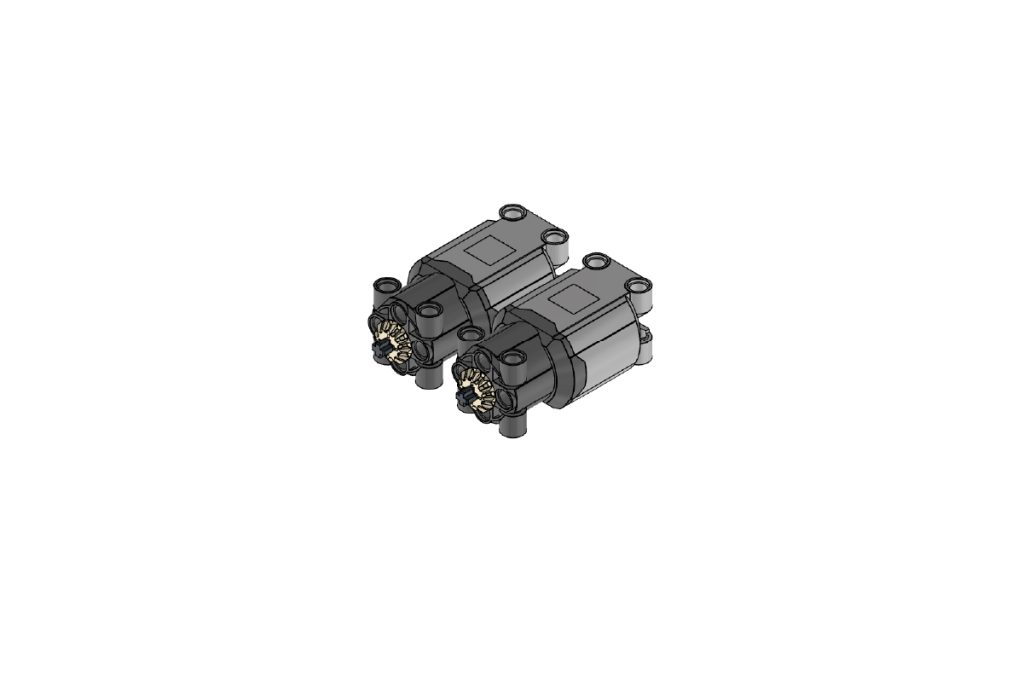
Place the two completed motor sub-assemblies side by side.
Confirm that:
- Both DC Motors are positioned in the same direction;
- Both Bevel Gear 12 Tooth parts are aligned correctly, and both motor sub-assemblies are identical.
Step 4: Mount the Motors on the Main Frame
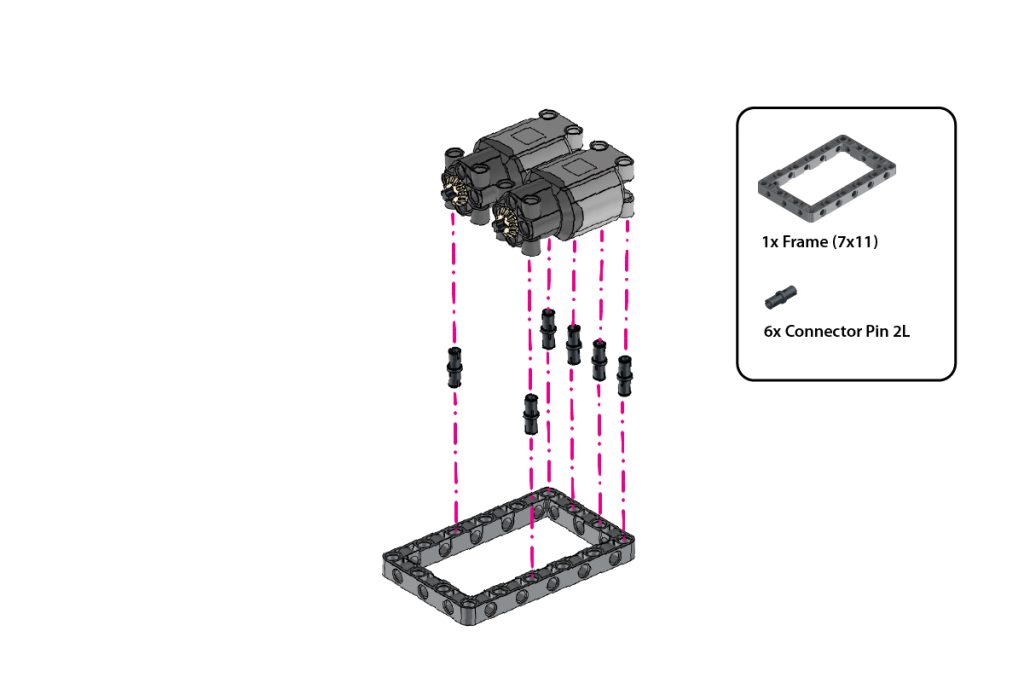
Take:
- one (1) Frame (7×11)
- Six (6) Connector Pin 2L (Black)
Insert the six Connector Pins 2L (Black) into the highlighted holes of the Frame (7×11).
Align the two motor sub-assemblies above the pins and press them firmly onto the frame.
Ensure both motors are securely fixed, evenly aligned, and positioned in the same direction, as shown in the image.
Step 5: Attach the Side T-Shape Beams
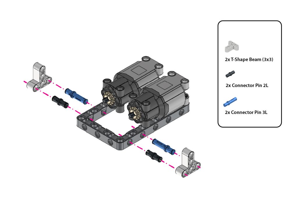
Take:
- two (2) T-Shape Beam (3×3)
- two (2) Connector Pin 2L (Black)
- two (2) Connector Pin 3L (Blue)
Insert one Connector Pin 2L (Black) and one Connector Pin 3L (Blue) into the highlighted side holes on each side of the Frame (7×11).
Attach one T-Shape Beam (3×3) to the exposed pins on the left side and the second T-Shape Beam (3×3) to the exposed pins on the right side.
Press both beams firmly and ensure they remain symmetrical.
Step 6: Complete the Front Support Structure
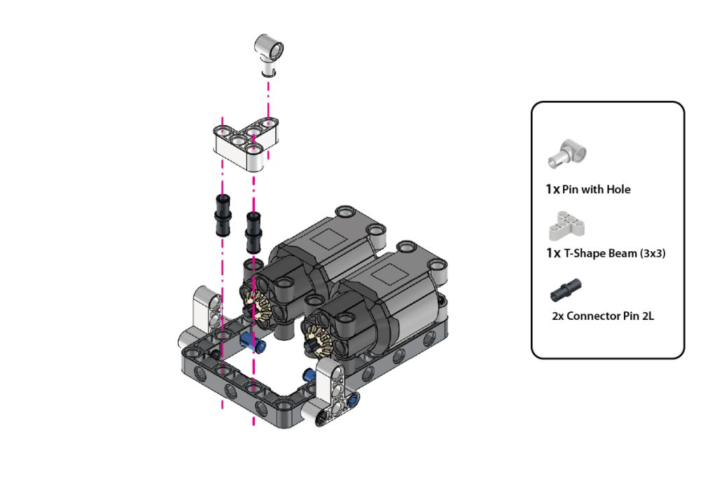
Take:
- one (1) Pin with Hole
- one (1) T-Shape Beam (3×3)
- two (2) Connector Pin 2L (Black)
Insert the Connector Pin 2L (Black) into the highlighted mounting holes.
Attach the one T-Shape Beams (3×3) in the orientation shown in the image.
Fit one Pin with Hole onto each T-shape beam. Ensure both supports are securely connected and aligned evenly on both sides.
Step 7: Install the First Drive Axle and Gear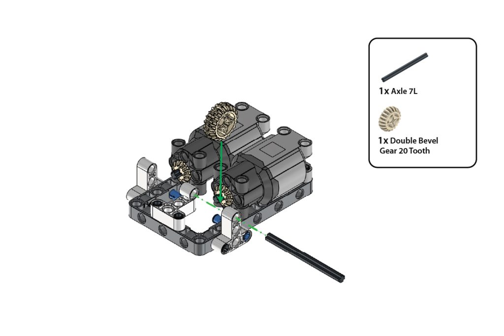
Take:
- one (1) Axle 7L
- one (1) Double Bevel Gear 20 Tooth
Insert the Axle 7L through the aligned holes of the first side support and motor assembly.
Slide the Double Bevel Gear 20 Tooth onto the axle and position it so that it meshes correctly with the Bevel Gear 12 Tooth attached to the motor.
Ensure the axle rotates freely and the gears engage smoothly.
Step 8: Install the Second Drive Axle and Gear
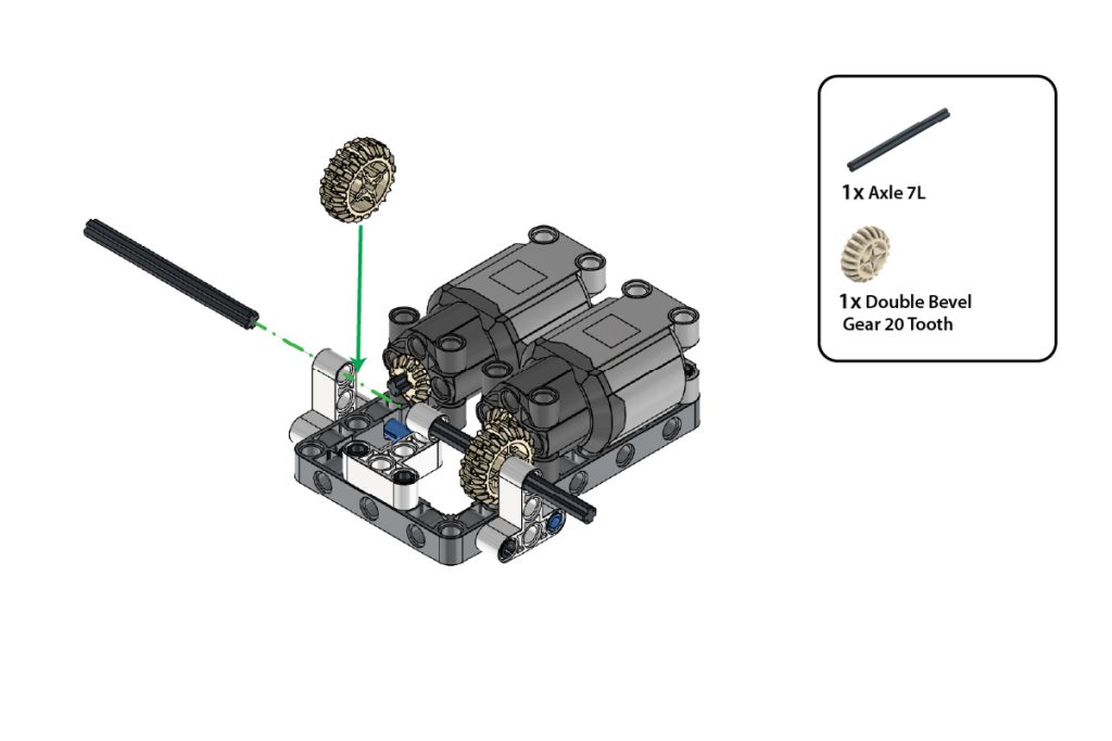
Take:
- one (1) Axle 7L
- one (1) Double Bevel Gear 20 Tooth
Repeat Step 7 on the opposite side of the chassis.
Insert the second Axle 7L through the aligned holes and attach the remaining Double Bevel Gear 20 Tooth.
Ensure both drive assemblies rotate smoothly and remain symmetrical.
Step 9: Attach the Cross Beam Support
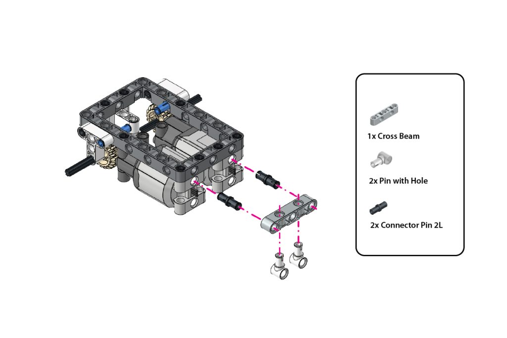
Take:
- one (1) Cross Beam
- two (2) Pin with Hole
- two (2) Connector Pin 2L (Black)
Insert the two Connector Pin 2L (Black) into the highlighted holes at the end of the Frame (7×11).
Align the Cross Beam with the exposed pins and press it firmly into place.
Insert the two Pin with Hole into the highlighted holes of the Cross Beam, with their circular holes facing downward, as shown in the image.
Step 10: Attach the Castor Wheel
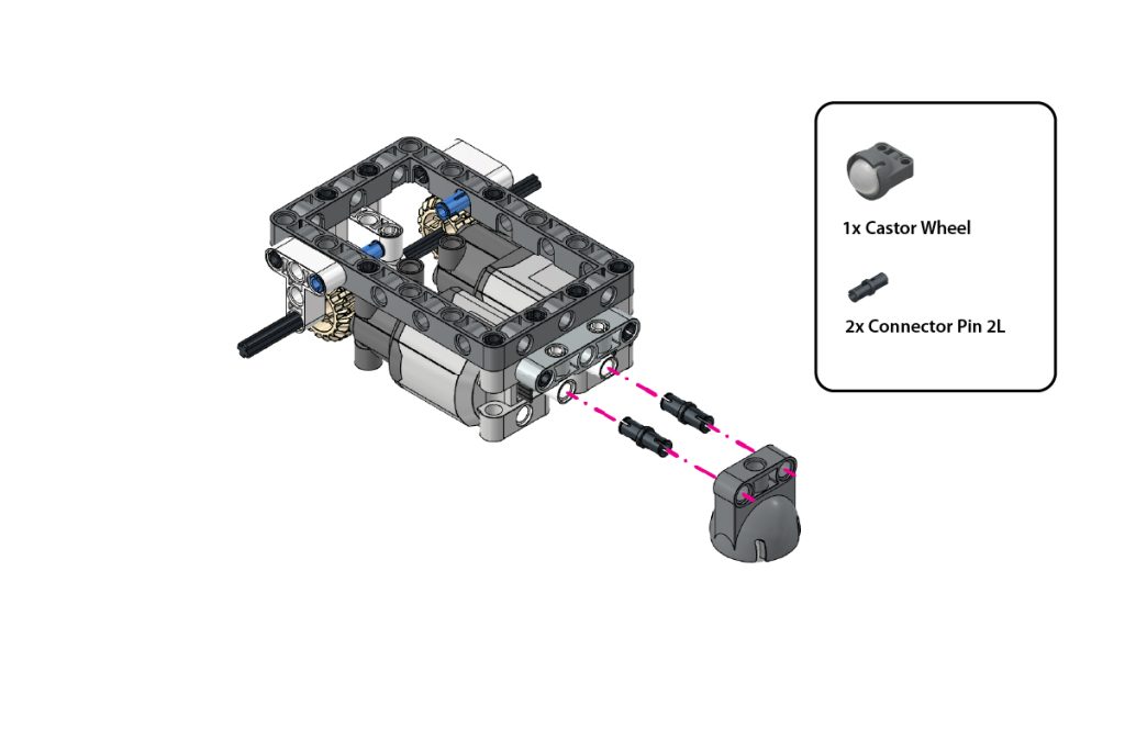
Take:
- one (1) Castor Wheel
- two (2) Connector Pin 2L (Black)
Insert the two Connector Pin 2L (Black) into the highlighted mounting holes of the Castor Wheel.
Align the Castor Wheel with the two Pin with Hole attached in the previous step.
Press the Castor Wheel firmly into place and ensure it is centred and able to rotate freely.
Step 11: Install the Drive Wheels
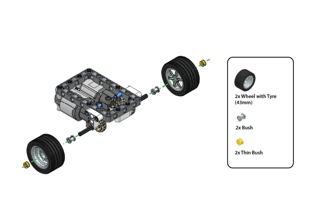
Take:
- two (2) Wheel with Tyre (43 mm)
- two (2) Bush
- two (2) Thin Bush
Slide one Bush onto each exposed Axle 7L.
Attach one Wheel with Tyre (43 mm) to each axle.
Secure each wheel by pressing one Thin Bush onto the outer end of the axle.
Ensure both wheels are firmly mounted but can rotate freely.
Step 12: Verify the Chassis Assembly
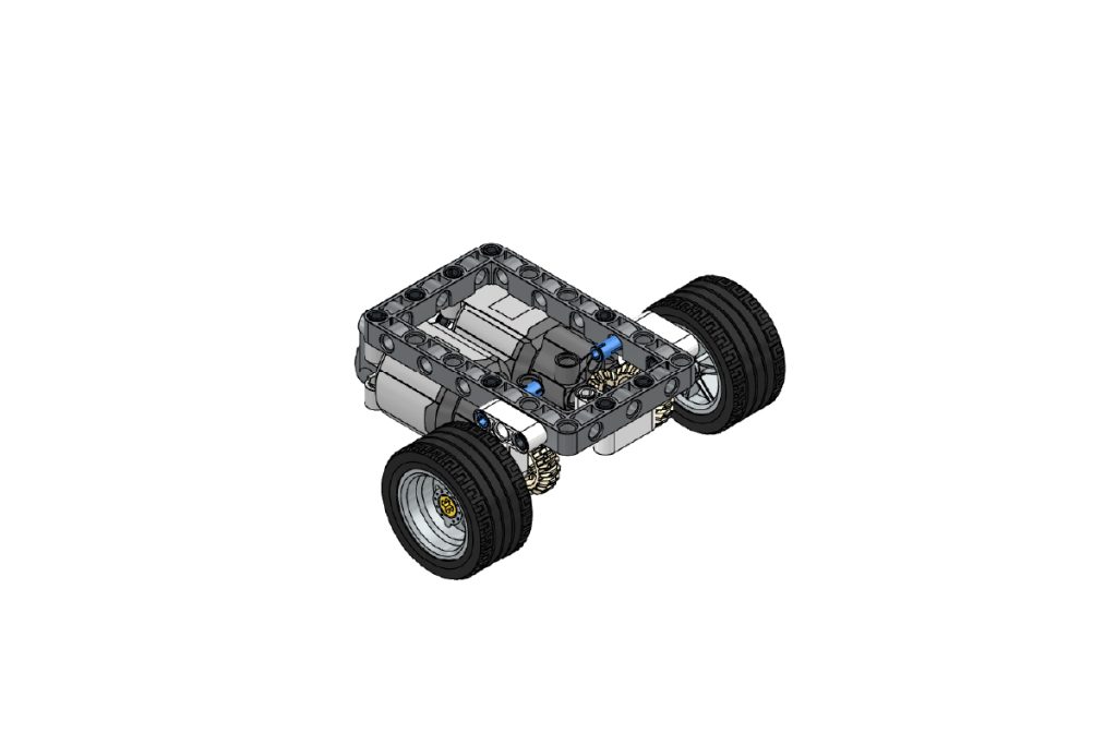
Check the completed chassis assembly.
Ensure that:
- Both drive wheels are aligned;
- The Castor Wheel rotates freely;
- Both motor gears mesh correctly;
- Both motors are securely attached, and
- The chassis remains level and stable.
Step 13: Attach the Upper Mounting Pins
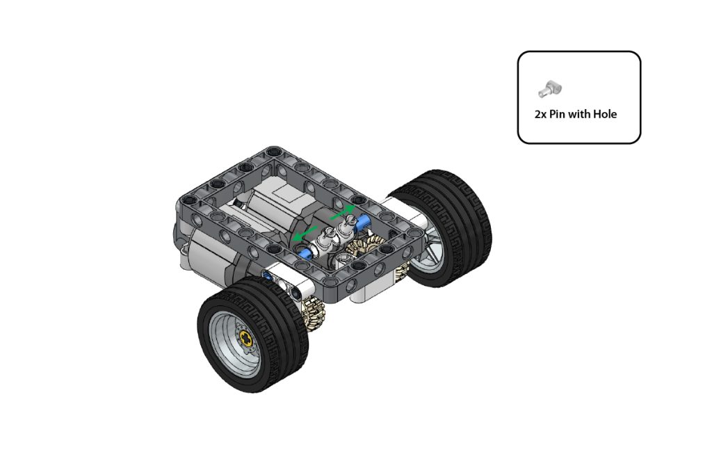
Take:
- two (2) Pin with Hole
Attach the two Pin with Hole to the exposed Connector Pin 3L (Blue) inside the chassis.
Position them in the direction shown by the arrows in the image.
Press both parts firmly and ensure they remain aligned, as these connections will support the upper frame assemblies.
Step 14: Prepare the First Upper Frame
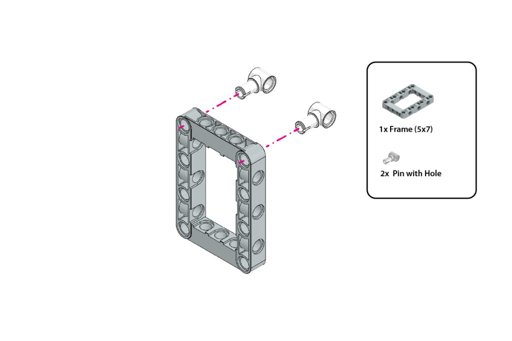
Take:
- one (1) Frame (5×7)
- two (2) Pin with Hole
Insert one Pin with Hole into each highlighted top corner hole of the Frame (5×7).
Ensure both Pin with Hole parts face outward and are positioned symmetrically, as shown in the image.
Step 15: Attach the Second Frame and First Bent Beam
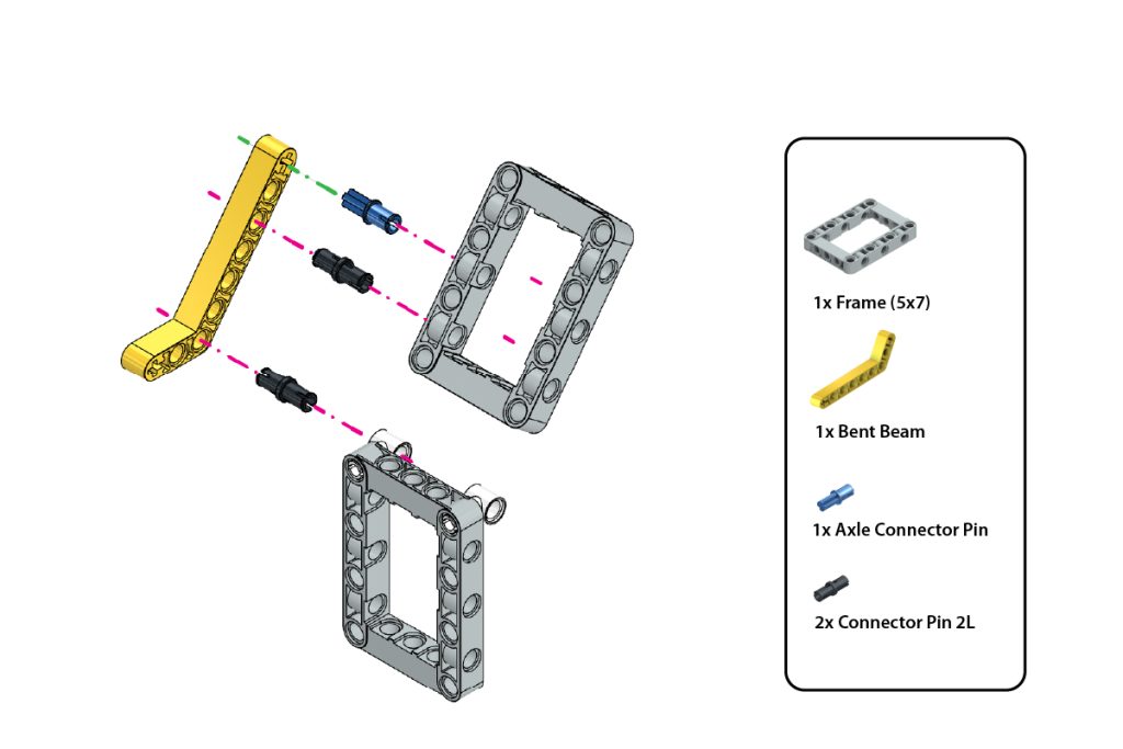
Take:
- one (1) Frame (5×7)
- one (1) Bent Beam
- one (1) Axle Connector Pin (Blue)
- two (2) Connector Pin 2L (Black)
Position the second Frame (5×7) above the frame prepared in Step 14.
Insert the Axle Connector Pin (Blue) and two Connector Pin 2L (Black) into the highlighted holes of the Bent Beam.
Align the pins with the corresponding holes of both frames and press them firmly into place.
Maintain the exact angle and orientation shown in the image.
Step 16: Attach the Second Bent Beam
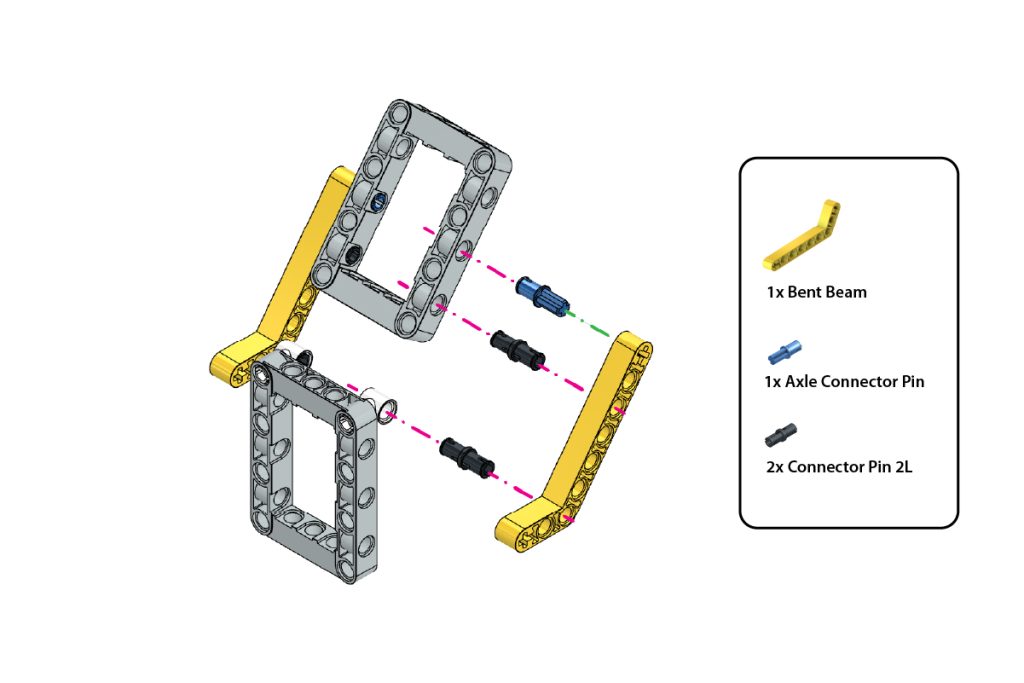
Take:
- one (1) Bent Beam
- one (1) Axle Connector Pin (Blue)
- two (2) Connector Pin 2L (Black)
Repeat the previous step on the opposite side of the upper-frame assembly.
Attach the second Bent Beam using the Axle Connector Pin (Blue) and two Connector Pin 2L (Black).
Ensure both Bent Beams are positioned symmetrically and support the upper Frame evenly.
Step 17: Attach the First Vertical Beam
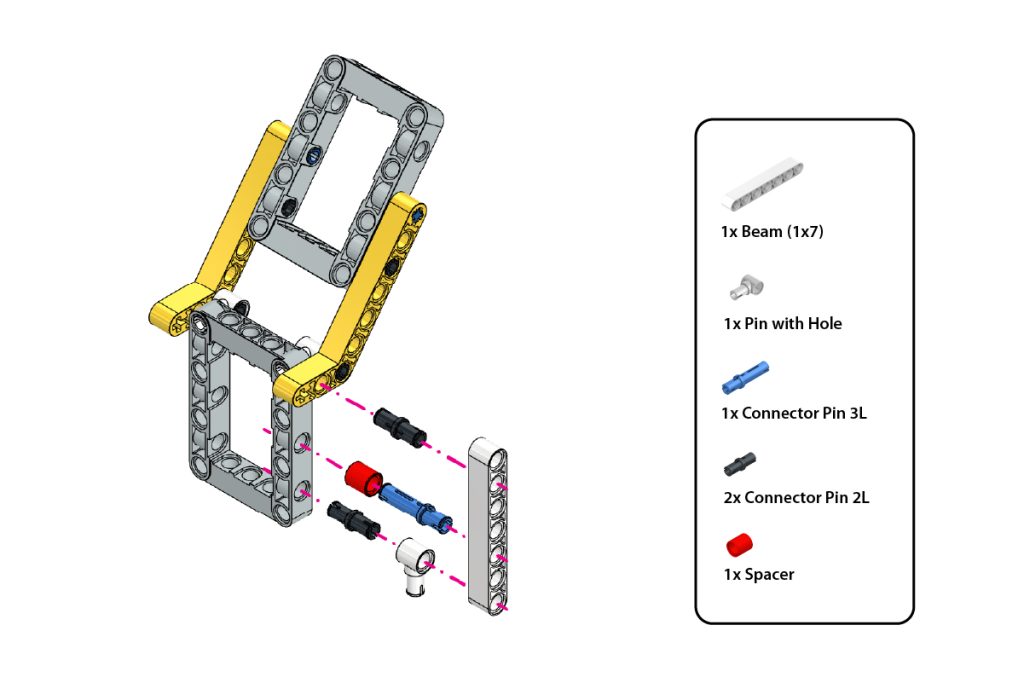
Take:
- one (1) Beam (1×7)
- one (1) Pin with Hole
- one (1) Connector Pin 3L (Blue)
- two (2) Connector Pin 2L (Black)
- one (1) Spacer
Insert the Pin with Hole into the bottom hole of the Beam (1×7).
Slide the Spacer onto the Connector Pin 3L (Blue).
Insert the Connector Pin 3L with the Spacer into the highlighted middle hole of the Beam.
Insert the two Connector Pin 2L (Black) into the remaining highlighted holes.
Align the Beam with the corresponding holes on one side of the upper-frame assembly and press all connections firmly into place.
Step 18: Attach the Second Vertical Beam
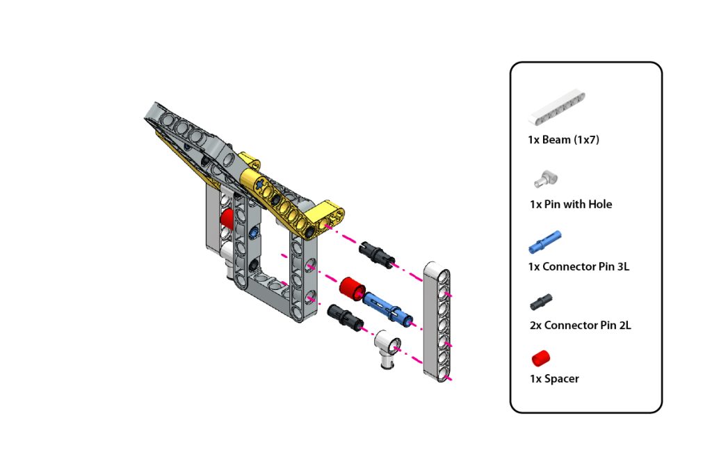
Take:
- one (1) Beam (1×7)
- one (1) Pin with Hole
- one (1) Connector Pin 3L (Blue)
- two (2) Connector Pin 2L (Black)
- one (1) Spacer
Repeat Step 17 on the opposite side of the upper-frame assembly.
Ensure both Beam (1×7) parts are attached symmetrically and that the Pin with Hole connections face downward, as shown in the image.
Step 19: Repeat the Upper-Frame Assembly on the Opposite Side
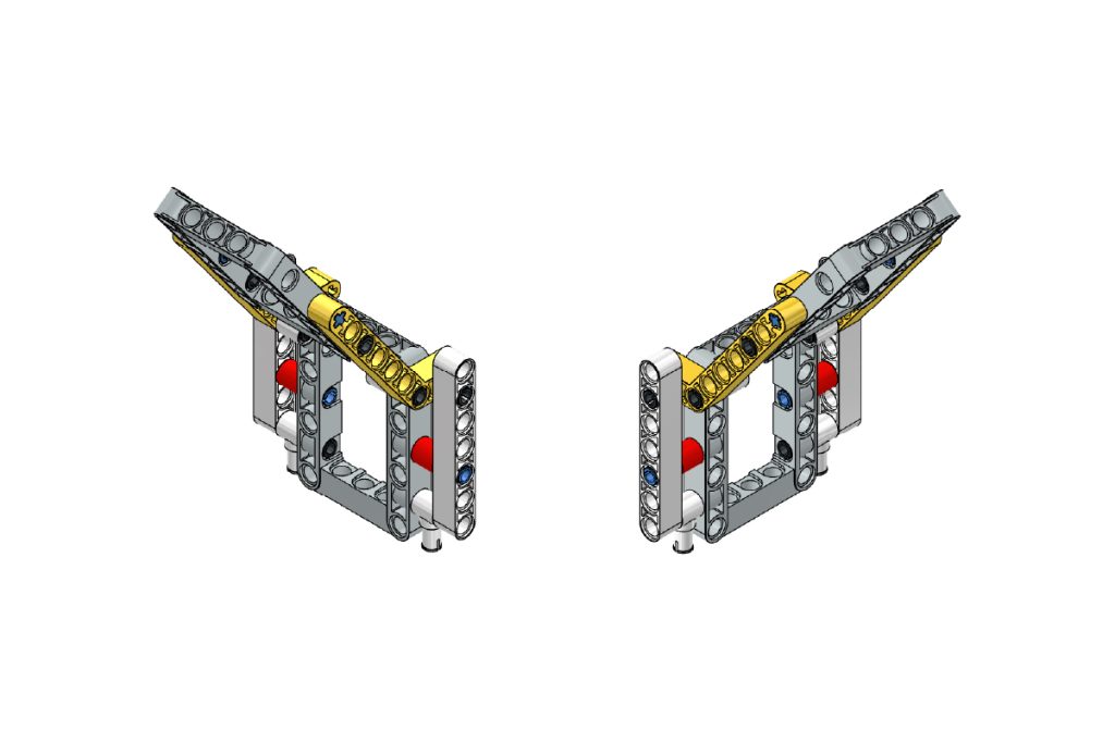
Using the remaining components, repeat Steps 15–18 on the opposite side to create a matching upper-frame structure.
Ensure that:
- Both Bent Beams are mounted in the same orientation as shown in the image.
- Both Beam (1×7) assemblies are positioned symmetrically.
- All Pin with Hole connections face in the correct direction.
- The Spacer and Connector Pins are installed in the same positions on both sides.
- Both upper-frame structures are aligned evenly and maintain the same angle.
After completing this step, the upper-frame assembly should appear symmetrical on both sides and match the configuration shown in the image.
Step 20: Mount the Upper Frames on the Chassis
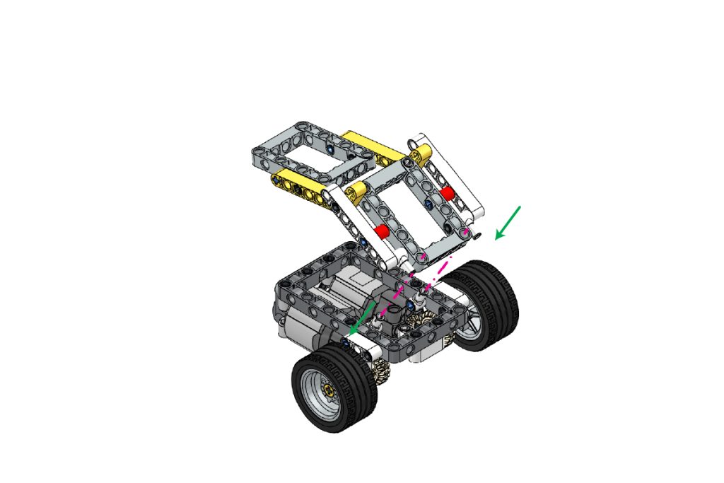
Take the two completed upper-frame sub-assemblies and position them above the chassis.
Align the lower Pin with Hole connections of the upper frames with the mounting points prepared on the chassis.
Lower the upper-frame assemblies carefully and press them firmly into place.
Ensure that:
- Both upper frames are securely attached;
- Both sides are symmetrically aligned;
- The frames maintain the angle shown in the image, and
- The joints move smoothly without obstruction.
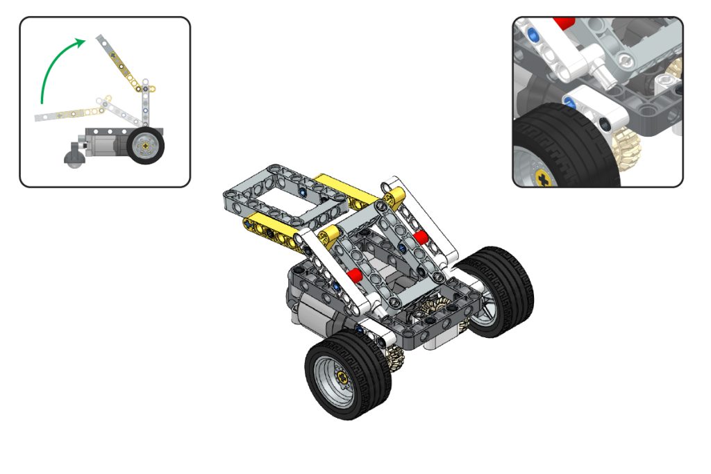
Step 21: Attach the Mini Expansion Board
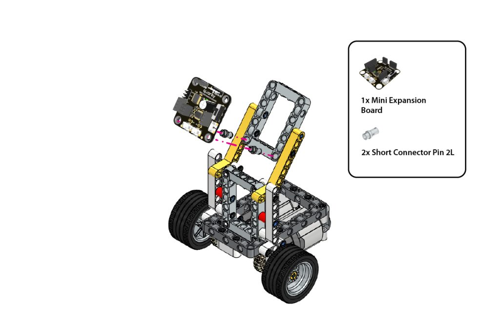
Take:
- one (1) Quarky Mini Expansion Board
- two (2) Short Connector Pin
Place the Quarky Mini Expansion Board on the designated upper-frame mounting area.
Align its mounting holes with the highlighted holes on the frame.
Insert one Short Connector Pin into each mounting point and press firmly until the board is securely fixed, remains level, and matches the required orientation.
Step 22: Attach Quarky Intellio
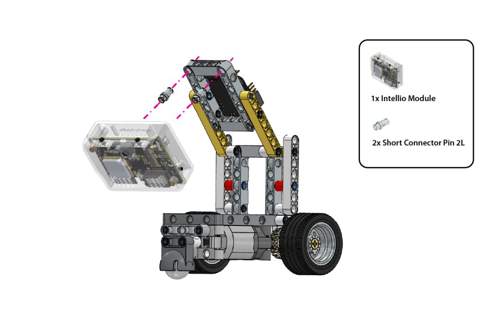
Take:
- one (1) Quarky Intellio
- two (2) Short Connector Pin
Position Quarky Intellio on the remaining upper-frame mounting area.
Align the mounting holes of Quarky Intellio with the corresponding holes on the frame.
Insert the two Short Connector Pin and press them firmly until Quarky Intellio is securely mounted.
Ensure its camera faces forward and remains unobstructed.
Step 23: Verify the Final Assembly
Check the completed Lane Follower Robot.
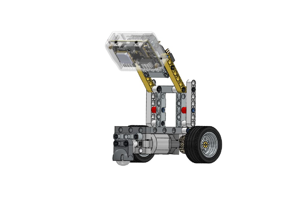
Ensure that:
- Quarky Intellio is securely mounted;
- The Mini Expansion Board is fixed firmly;
- The camera faces forward at the correct angle;
- Both upper frames are symmetrical;
- The wheels and gears rotate smoothly;
- The Castor Wheel moves freely, and
- There are no loose beams, pins, or connectors.
The mechanical assembly of the Quarky Intellio Lane Follower Robot is now complete.
Connect the Electronics and Set Up the Lane Follower Program
After completing the mechanical assembly, connect Quarky Intellio, the Mini Expansion Board, and both DC Motors. Then open the provided Lane Follower program in PictoBlox, install the required Python packages, configure the network settings, and run the robot.
Step 24: Connect Quarky Intellio to the Mini Expansion Board
Connect Quarky Intellio to the Mini Expansion Board according to the wiring diagram.
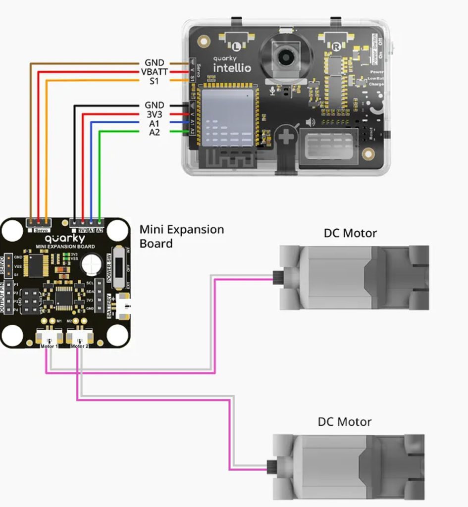
Ensure that every wire is connected to the matching labelled pin and follows the same orientation shown in the wiring diagram.
Step 25: Download the Lane Follower Program
Download the provided Lane-Follower-Robot Python project file and save it in an easily accessible folder on your computer.
Remember the saved location, as you will need to open the file in PictoBlox.
Step 26: Open the Program in PictoBlox
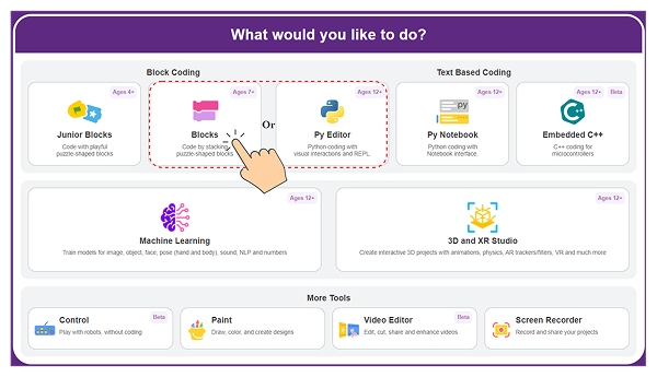
- Open PictoBlox and choose Blocks or Py Editor.
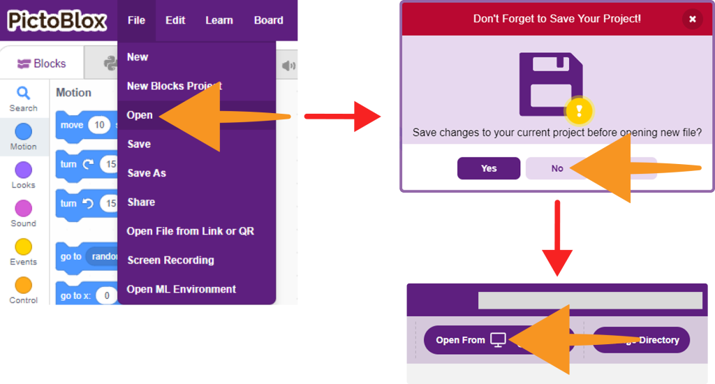
- Use the Open option to browse to the downloaded Lane Follower project file, select the file, and open it.
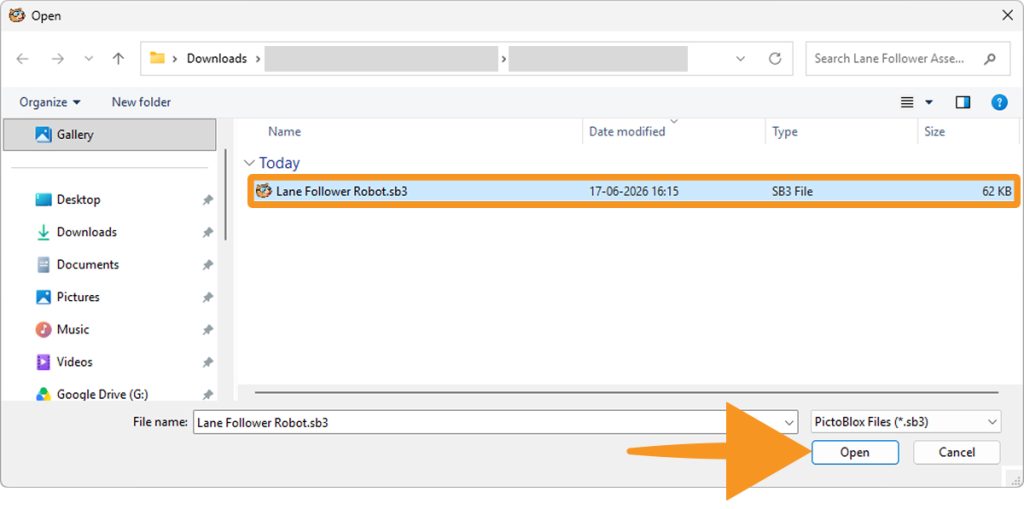
- Confirm that the complete Python program appears in the editor.
# ================= IMPORTING LIBRARIES =================
import cv2
import numpy as np
import socket
import threading
import time
import math

# ================= INITIALIZING THE ROBOT AND OBJECT DETECTION =================

# initialize the Mini Expansion board.
mini = QuarkyMiniExpansion()
mini.miniinitialise()

# using the Object Detection Extension
od = ObjectDetection()
od.enablebox()
od.setthreshold(0.4)

# ================= CONFIGURATION =================

STREAM_PORT = 6000
LOCALHOST = "127.0.0.1"
MAX_UDP_PACKET = 65536

# ================= MOTOR SPEED LIMITS =================

MAX_SPEED = 100
MIN_SPEED = 0

# ================= CONTROLLER SETTINGS =================

# Kp controls how strongly the robot reacts to its current error.
# Larger Kp = stronger correction.
DEFAULT_KP = 0.34

# Kd would normally control how strongly the robot reacts to changes in the error.
DEFAULT_KD = 0.10

# Controls how strongly the robot turns.
DEFAULT_TURN_GAIN = 0.13

# ================= MOTOR CONTROL SETTINGS =================

DEFAULT_BASE_SPEED = 17
diff = 5
DEFAULT_MOTOR_GAIN = 0.2

# ================= CENTER OFFSET SETTINGS =================

DEFAULT_CENTER_OFFSET = 0
CENTER_OFFSET_RANGE = 50

# ================= SMOOTHING SETTINGS =================

# alpha controls smoothing.
alpha = 0.3
smoothed_target_x = None

# ================= IMAGE / CONTOUR FILTERING =================

# This helps prevent camera noise from being treated as a lane.
MIN_CONTOUR_AREA = 150
kernel = np.ones((5, 5), np.uint8)

# ================= LANE WIDTH ESTIMATION =================

last_lane_width_est = 60.0
lane_width_alpha = 0.2

# ================= VIDEO RECEIVER =================

# This class is responsible for receiving the camera video.
class VideoReceiver:
    def __init__(self, port):
        self.sock = socket.socket(socket.AF_INET, socket.SOCK_DGRAM)
        self.sock.bind((LOCALHOST, port))
        self.sock.settimeout(1.0)
        self.latest_frame = None
        self.running = True
        self.lock = threading.Lock()
        self.thread = threading.Thread(target=self.receive_loop)
        self.thread.daemon = True
        self.thread.start()
        print(f"UDP Video Receiver listening on {LOCALHOST}:{port}")

    # This function continuously waits for camera data.
    def receive_loop(self):
        current_buffer = bytearray()
        expected_size = 0
        while self.running:
            try:
                data, _ = self.sock.recvfrom(MAX_UDP_PACKET)
                if data.startswith(b"SIZE:"):
                    try:
                        expected_size = int(data[5:].decode())
                        # Start with an empty buffer for this frame.
                        current_buffer = bytearray()
                    except:
                        expected_size = 0
                elif expected_size > 0:
                    current_buffer.extend(data)
                    if len(current_buffer) >= expected_size:
                        np_arr = np.frombuffer(current_buffer, dtype=np.uint8)
                        frame = cv2.imdecode(np_arr, cv2.IMREAD_COLOR)
                        if frame is not None:
                            with self.lock:
                                self.latest_frame = frame

                        expected_size = 0
                        current_buffer = bytearray()

            except socket.timeout:
                continue
            except Exception as e:
                print(f"Receiver Error: {e}")

    # GET THE MOST RECENT CAMERA IMAGE
    def get_frame(self):
        with self.lock:
            return self.latest_frame

    # STOP THE VIDEO RECEIVER
    def stop(self):
        self.running = False
        self.sock.close()

# ================= HELPER FUNCTIONS =================
def nothing(x):
    pass

def centroid_from_contour(c):
    M = cv2.moments(c)
    if M['m00'] == 0:
        return None
    cx = int(M['m10']/M['m00'])
    cy = int(M['m01']/M['m00'])
    return (cx, cy)

def slice_centroids(mask, y_top, y_bottom, slice_name="Slice"):
    h, w = mask.shape
    y_top = max(0, min(h-1, int(y_top)))
    y_bottom = max(0, min(h, int(y_bottom)))
    if y_bottom <= y_top:
        return []

    slice_img = mask[y_top:y_bottom, :]
    contours, _ = cv2.findContours(slice_img, cv2.RETR_EXTERNAL, cv2.CHAIN_APPROX_SIMPLE)
    centroids = []

    corrected_y_coords = []

    for c in contours:
        if cv2.contourArea(c) >= MIN_CONTOUR_AREA:
            cent = centroid_from_contour(c)
            if cent:
                cx, cy_relative = cent
                cy_global = y_top + cy_relative
                centroids.append((cx, cy_global))
                corrected_y_coords.append(cy_global)

    if corrected_y_coords and slice_name != "SkipPrint":
        print(f"{slice_name} Centroid Y-Coordinates: {corrected_y_coords}")

    return centroids

# ================= CREATE  THE TUNING WINDOW AND SLIDERS =================

receiver = VideoReceiver(STREAM_PORT)

cv2.namedWindow("Tuning", cv2.WINDOW_NORMAL)
cv2.resizeWindow("Tuning", 800, 600)

cv2.createTrackbar("Black Threshold", "Tuning", 100, 255, nothing)
cv2.createTrackbar("Kp x100", "Tuning", int(DEFAULT_KP*100), 300, nothing)
cv2.createTrackbar("Kd x100", "Tuning", int(DEFAULT_KD*100), 200, nothing)
cv2.createTrackbar("TurnGain x100", "Tuning", int(DEFAULT_TURN_GAIN*100), 300, nothing)
cv2.createTrackbar("Base Speed", "Tuning", DEFAULT_BASE_SPEED, MAX_SPEED, nothing)
cv2.createTrackbar("Motor Gain x100", "Tuning", int(DEFAULT_MOTOR_GAIN*100), 100, nothing)
cv2.createTrackbar("Center Offset", "Tuning", DEFAULT_CENTER_OFFSET + CENTER_OFFSET_RANGE, 2*CENTER_OFFSET_RANGE, nothing)
cv2.createTrackbar("Bottom Ignore %", "Tuning", 10, 40, nothing)
cv2.createTrackbar("Far ROI top %", "Tuning", 15, 60, nothing)
cv2.createTrackbar("Far ROI bottom %", "Tuning", 39, 80, nothing)
cv2.createTrackbar("Near ROI top %", "Tuning", 42, 90, nothing)
cv2.createTrackbar("Left Region Center %", "Tuning", 12, 50, nothing)
cv2.createTrackbar("Left Region Width %", "Tuning", 29, 50, nothing)
cv2.createTrackbar("Right Region Center %", "Tuning", 86, 100, nothing)
cv2.createTrackbar("Right Region Width %", "Tuning", 27, 50, nothing)

# ================= MAIN ROBOT LOOP =================

while True:
    frame = receiver.get_frame()
    if frame is None:
        mini.stoprobot()
        time.sleep(0.01)
        continuE

    try:
        frame = cv2.resize(frame, (320, 240))
        h, w = frame.shape[:2]

# ================= READ CURRENT SLIDER VALUES =================

        thresh_val = cv2.getTrackbarPos("Black Threshold", "Tuning")
        Kp = cv2.getTrackbarPos("Kp x100", "Tuning") / 100.0
        Kd = cv2.getTrackbarPos("Kd x100", "Tuning") / 100.0
        turn_gain = cv2.getTrackbarPos("TurnGain x100", "Tuning") / 100.0
        base_speed = cv2.getTrackbarPos("Base Speed", "Tuning")
        motor_gain = cv2.getTrackbarPos("Motor Gain x100", "Tuning") / 100.0

# ================= FIND DESIRED CENTER =================

        raw_offset = cv2.getTrackbarPos("Center Offset", "Tuning")
        center_offset = raw_offset - CENTER_OFFSET_RANGE
        TARGET_CENTER_X = w // 2 + center_offset

# ================= READ REGION SETTINGS =================

        bottom_ignore_pct = cv2.getTrackbarPos("Bottom Ignore %", "Tuning") / 100.0
        far_top_pct = cv2.getTrackbarPos("Far ROI top %", "Tuning") / 100.0
        far_bottom_pct = cv2.getTrackbarPos("Far ROI bottom %", "Tuning") / 100.0
        near_top_pct = cv2.getTrackbarPos("Near ROI top %", "Tuning") / 100.0

# ================= LEFT / RIGHT REGION SETTINGS ================

        left_center_pct = cv2.getTrackbarPos("Left Region Center %", "Tuning") / 100.0
        left_width_pct = max(1, cv2.getTrackbarPos("Left Region Width %", "Tuning")) / 100.0
        right_center_pct = cv2.getTrackbarPos("Right Region Center %", "Tuning") / 100.0
        right_width_pct = max(1, cv2.getTrackbarPos("Right Region Width %", "Tuning")) / 100.0

# ================= CONVERT CAMERA IMAGE INTO BLACK/WHITE =================

        gray = cv2.cvtColor(frame, cv2.COLOR_BGR2GRAY)
        _, mask = cv2.threshold(gray, thresh_val, 255, cv2.THRESH_BINARY_INV)
        mask = cv2.morphologyEx(mask, cv2.MORPH_OPEN, kernel)
        mask = cv2.morphologyEx(mask, cv2.MORPH_CLOSE, kernel)

# ================= CALCULATE IMAGE REGIONS =================

        bottom_ignore = int(h * bottom_ignore_pct)
        far_top = int(h * far_top_pct)
        far_bottom = int(h * far_bottom_pct)
        near_top = int(h * near_top_pct)
        near_bottom = h - bottom_ignore

# ================= FIND LANE MARKERS =================

        near_centroids = slice_centroids(mask, near_top, near_bottom, "SkipPrint")
        far_centroids = slice_centroids(mask, far_top, far_bottom, "SkipPrint")
        debug = frame.copy()
        cv2.rectangle(debug, (0, far_top), (w-1, far_bottom), (200, 200, 0), 1)
        cv2.rectangle(debug, (0, near_top), (w-1, near_bottom), (200, 200, 0), 1)

# ================= SEPARATE LEFT AND RIGHT MARKERS =================

        left = []
        right = []
        if near_centroids:
            left = [c for c in near_centroids if c[0] < w//2]
            right = [c for c in near_centroids if c[0] >= w//2]

        left_marker = None
        right_marker = None
        if left:
            left_marker = max(left, key=lambda x: x[0])
            cv2.circle(debug, left_marker, 5, (0,0,255), -1)
        if right:
            right_marker = min(right, key=lambda x: x[0])
            cv2.circle(debug, right_marker, 5, (0,0,255), -1)

# ================= ESTIMATE LANE WIDTH =================

        if left_marker and right_marker:
            measured_width = abs(right_marker[0] - left_marker[0])
            last_lane_width_est = (lane_width_alpha * measured_width) + (1 - lane_width_alpha) * last_lane_width_est

# ================= CREATE LEFT AND RIGHT TARGET REGIONS =================

        left_region_center_x = int(left_center_pct * w)
        left_region_half_w = int((left_width_pct * w) / 2)
        left_region_x1 = max(0, left_region_center_x - left_region_half_w)
        left_region_x2 = min(w-1, left_region_center_x + left_region_half_w)

        right_region_center_x = int(right_center_pct * w)
        right_region_half_w = int((right_width_pct * w) / 2)
        right_region_x1 = max(0, right_region_center_x - right_region_half_w)
        right_region_x2 = min(w-1, right_region_center_x + right_region_half_w)

# ================= DRAW TARGET REGIONS =================

        overlay = debug.copy()
        alpha_overlay = 0.35
        cv2.rectangle(overlay, (left_region_x1, near_top), (left_region_x2, near_bottom), (255, 0, 0), -1)
        cv2.rectangle(overlay, (right_region_x1, near_top), (right_region_x2, near_bottom), (255, 0, 255), -1)
        cv2.addWeighted(overlay, alpha_overlay, debug, 1 - alpha_overlay, 0, debug)

        # CALCULATE POSITION ERROR
        # This list will store how far each detected marker is from its desired position.
        errors = []
        if left_marker:
            left_err = left_marker[0] - left_region_center_x
            errors.append(left_err)
        if right_marker:
            right_err = right_marker[0] - right_region_center_x
            errors.append(right_err)

        # If neither side of the lane was found, stop the robot

        if (not left_marker) and (not right_marker):
            mini.stoprobot()
            cv2.imshow("Mask", mask)
            cv2.imshow("Debug", debug)

            # If the user presses Q, exit the program.
            if cv2.waitKey(1) & 0xFF == ord('q'):
                break
            continue

        avg_error = sum(errors) / len(errors) if errors else 0.0

        # Multiply the error by Kp.
        # Larger error -> stronger correction.
        # Smaller error -> smaller correction.
        p_control_signal = Kp * avg_error
        speed_adjustment = motor_gain * p_control_signal

        # If the robot needs to correct its direction, one motor becomes slower and other becomes fast
        motor1_speed = base_speed - speed_adjustment
        motor2_speed = base_speed + speed_adjustment

        mini.runbothmotors('1','1',int(motor1_speed), int(motor2_speed))

        # SHOW DEBUGGING WINDOWS
        cv2.imshow("Mask", mask)
        cv2.imshow("Debug", debug)

        # Save the current error for possible future control logic.
        prev_error = avg_error

        if cv2.waitKey(1) & 0xFF == ord('q'):
            break

        time.sleep(0.070)

    # If something unexpected goes wrong inside the main loop, stop the robot.
    except Exception as ex:
        print("Loop Error:", ex)
        mini.stoprobot()

# ================= CLEANUP =================

# Stop the robot and receiving video feed
receiver.stop()
mini.stoprobot()
cv2.destroyAllWindows()
Do not use Block Coding for this example because the Lane Follower program is written in Python.
How the Lane Follower Code Works
The Python program continuously follows this process:
Receive Camera Frame → Process Image → Detect Lane → Calculate Error → Calculate Correction → Control Motors → Repeat
The robot does not move blindly. It repeatedly analyses the latest camera frame, detects where the lane is located, calculates how far it has moved away from the expected position, and adjusts the motors to steer back towards the lane.
The program works in these main stages:
- Initialise Quarky and Camera: The program initialises the Mini Expansion Board and starts receiving the live camera stream from Quarky Intellio.
- Process the Camera Feed: Each frame is resized, converted to grayscale, and thresholded to detect the dark lane.
- Clean the Detection: Small noise and gaps are removed from the lane mask using image-processing operations.
- Detect Lane Position: The program identifies left and right lane markers from the selected Region of Interest.
- Calculate Lane Error: The detected lane-marker positions are compared with the expected left and right reference positions.
- Apply Motor Correction: The program uses Kp, Base Speed, and Motor Gain to calculate different speeds for the two motors.
- Display and Tune: The Mask and Debug windows show how the lane is being detected. The Tuning Window allows real-time adjustment of detection and movement parameters.
- Safety and Cleanup: If the lane is not detected, an error occurs, or the user presses Q, the robot stops safely, and OpenCV windows are closed.
OpenCV Python Functions Used in the Lane Follower
The current program uses OpenCV to process the camera image and identify the lane. The important functions used in the actual code are:
- cv2.resize() – Reduces the camera frame to 320 × 240 pixels. A smaller frame requires less processing.
- cv2.cvtColor() – Converts the colour image to grayscale so the program can work with brightness values.
- cv2.threshold() – Separates dark lane regions from the lighter background using the Black Threshold value.
- cv2.morphologyEx() – Cleans the thresholded image by removing small noise and closing small gaps.
- cv2.findContours() – Finds connected regions in the processed lane mask.
- cv2.contourArea() – Measures each detected region and ignores regions smaller than the minimum contour area.
- cv2.moments() – Calculates the centre point of a detected contour.
- cv2.rectangle() – Draws the Near ROI, Far ROI, and detection regions on the Debug window.
- cv2.circle() – Marks the detected left and right lane points.
- cv2.addWeighted() – Creates transparent overlays for the left and right detection regions.
- cv2.imshow() – Displays the processed Mask and Debug windows.
- cv2.waitKey() – Keeps the OpenCV windows active and checks whether Q has been pressed.
- cv2.createTrackbar() – Creates the adjustable controls in the Tuning Window.
Step 27: Connect Quarky Intellio to PictoBlox
Connect Quarky Intellio to PictoBlox using a Quarky Intellio Wi-Fi connection method.
Step 28: Install OpenCV and Required Python Packages
The program uses Python libraries for image processing, numerical operations, networking, threading, and timing.
Libraries used
# OpenCV: Processes the camera images and performs lane detection.
import cv2

# NumPy: Handles image arrays and numerical calculations.
import numpy as np

# Socket: Provides UDP network communication with Quarky Intellio.
import socket

# Threading: Allows the camera receiver to receive frames
# separately from the main lane-following loop.
import threading

# Time: Provides delays and timing control.
import time

# Math: Provides mathematical functions when required.
import math
If any of these dependencies are not already installed on your system, install them using the Install Pip Package option in PictoBlox.
- Open the Install Pip Package option in PictoBlox.
- Enter the name of the package you want to install, then click Install to begin the installation process.
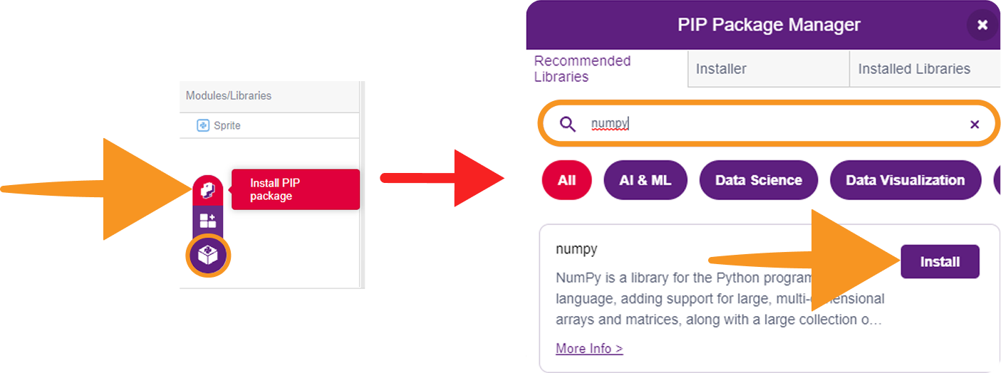
The following packages may need installation:
- opencv-python (for cv2)
- numpy
The opencv-python package is required for cv2, which is used for camera feed processing, lane detection, thresholding, contour detection, and visual output windows. The numpy package is used for numerical operations on image data and arrays.
The remaining libraries, socket, threading, time, and math, are included with Python by default and do not require separate installation.
Step 29: Run the Python OpenCV Lane Follower Program
Once Quarky Intellio is connected and all required packages are installed, run the Python script in PictoBlox.
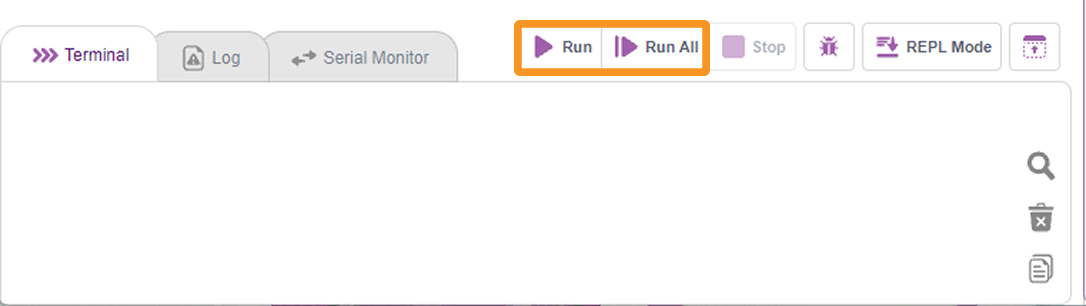
When the program starts, it:
- Creates the camera receiver.
- Creates the Tuning Window.
- Creates the tuning sliders.
- Initialises the Mini Expansion Board.
- Starts the main lane-following loop.
Understanding the Tuning Parameters
The Tuning Window provides several adjustable parameters. Some parameters directly affect the robot’s movement, while others are displayed for tuning or future use.
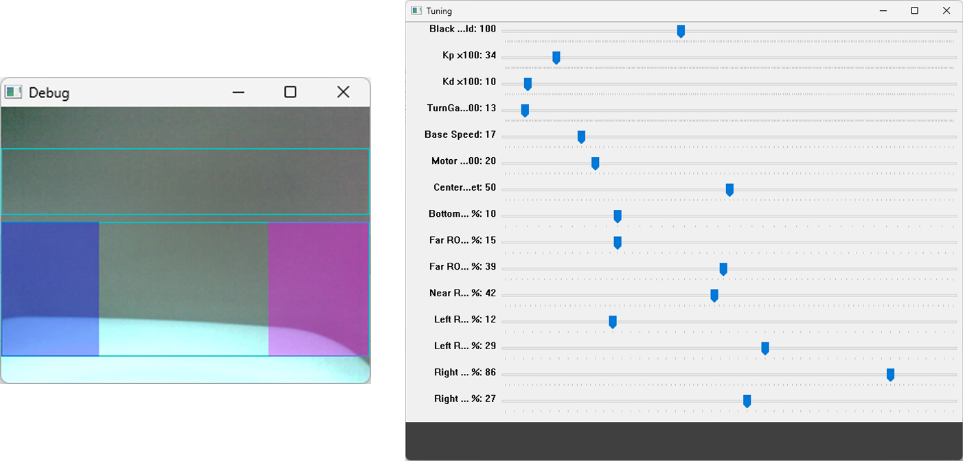
| Parameter | Function | What happens when you increase it? |
|---|---|---|
| Black Threshold | Decides which dark pixels are detected as the lane. | More light/grey areas may also be detected as the lane. |
| Kp | Controls how strongly the robot reacts to lane-position error. | The robot corrects more sharply when it moves away from the lane. |
| Base Speed | Sets the robot’s basic forward speed. | The robot moves faster, but may become harder to control on turns. |
| Motor Gain | Scales the steering correction applied to the motors. | The difference between the two motor speeds becomes larger, making turns stronger. |
| Bottom Ignore % | Ignores the bottom part of the camera frame while detecting the lane. | More of the nearest camera area is ignored. |
| Near ROI Top % | Sets where the active lane-detection area begins. | Detection starts farther down the camera frame. |
| Left Region Center % | Sets the expected position of the left lane marker. | The left reference position moves to the right. |
| Right Region Center % | Sets the expected position of the right lane marker. | The right reference position moves to the right. |
The sliders are read continuously inside the main loop, so changing an active parameter affects the program without restarting it. These values may need to be modified whenever the arena, lane width, lighting condition, or camera angle changes.
These tuning values help the OpenCV program accurately identify the lane and control the robot’s movement. If the robot is unable to follow the lane correctly, adjust the values gradually while observing the camera feed and lane-detection windows.
The tuning parameters may need to be modified whenever a different arena, lane width, or lighting condition is used.
Step 30: Place the Robot on the Lane Follower Arena
Take the prepared Lane Follower Arena and place it on a flat, well-lit, and non-reflective surface. Position the Quarky Intellio Lane Follower Robot at the starting point of the lane. Make sure the camera is facing forward and has a clear view of the lane.

Before testing, check the camera feed and confirm that the lane is clearly visible in the OpenCV output window.
Ensure that:
- The surface is flat.
- The lane has clear contrast against the background.
- The lighting is soft and even.
- Shadows do not cover the lane.
- There is no strong reflection on the arena.
- The camera has a clear forward view.
- The wheels can rotate freely.
- The robot has enough space to move safely.
Run the Program
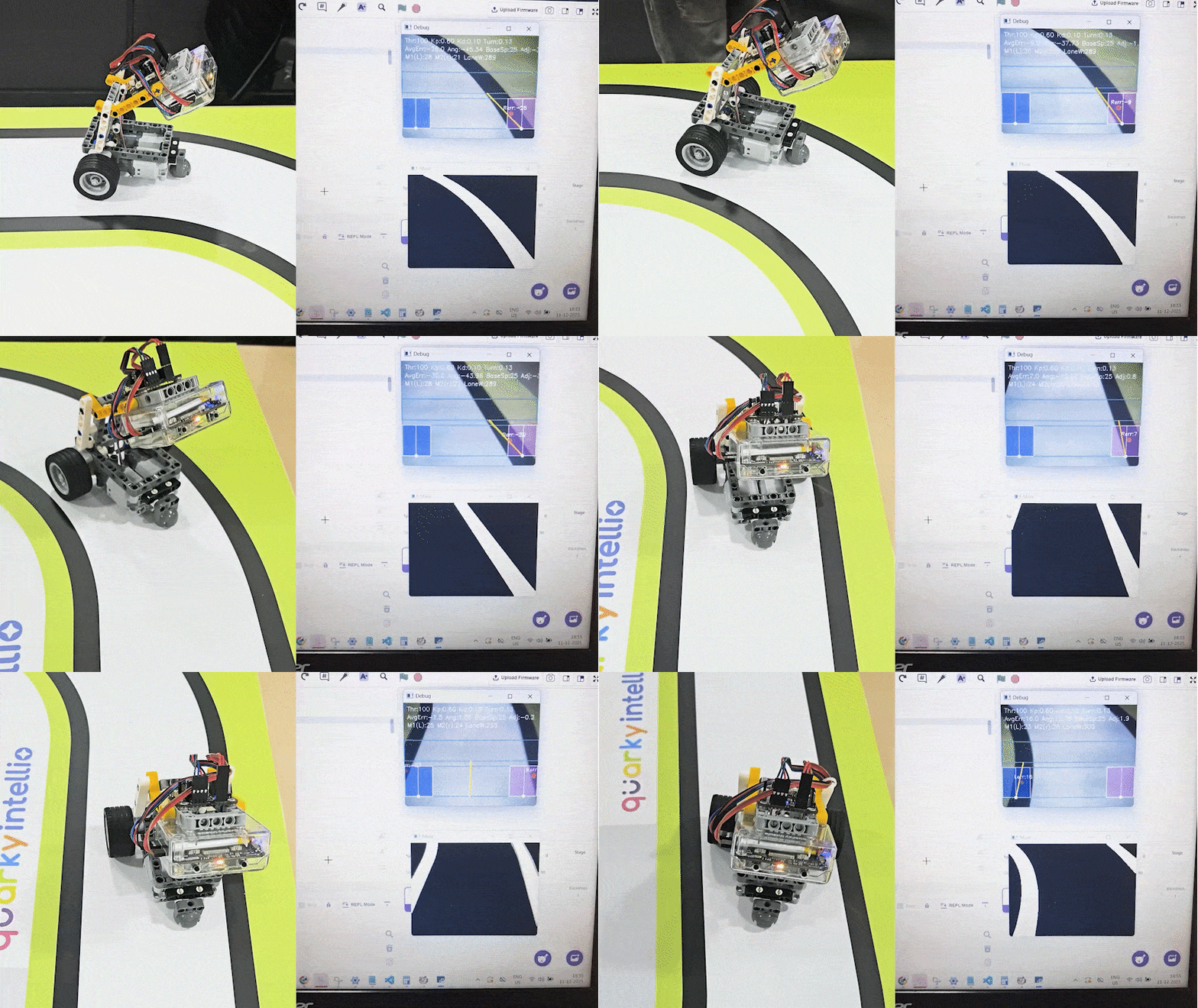
Run the Python program in PictoBlox.
Use the Tuning Window to adjust parameters such as Black Threshold, Kp, Kd, Base Speed, Turn Gain, and Region of Interest (ROI) if the robot does not follow the lane accurately. Adjust the values gradually and test the robot again until it follows the lane smoothly and consistently.
How OpenCV Helps the Quarky Intellio Lane Follower Robot
OpenCV is used in this project to process the live camera feed captured by Quarky Intellio. The robot does not simply move forward blindly. Instead, it continuously analyzes the lane visible in the camera frame and makes movement decisions based on the processed image.
The Python program uses OpenCV to convert the camera feed into a format suitable for lane detection, identify dark lane regions, calculate the lane position, and adjust the motor speed accordingly. This allows the robot to follow the lane autonomously.
In simple terms, OpenCV acts as the robot’s vision system. It helps Quarky Intellio “see” the lane, understand where the path is located, and decide whether to move forward, turn left, or turn right.
Troubleshooting Guide
While running the Quarky Intellio Lane Follower Robot, you may face issues related to motor direction, camera feed, lighting, or tuning values. Use the following troubleshooting steps to identify and fix the problem.
If the robot is not moving correctly or turns in the wrong direction.
To test the motors:
- Go to the Blocks section in PictoBlox.
- From the Mini Expansion Board, add the block to run motor 1 forward with 100 speed.
- Tap on the block and check whether Motor 1 moves forward.
- Repeat the same step for Motor 2 by changing the motor number from 1 to 2 and confirm that both motors move forward.
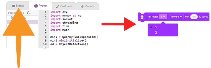
Both motors must move forward correctly for the lane-follower robot to follow the path.
Check Camera Streaming Resolution
The camera streaming resolution should be set to SVGA (800 × 600) for stable lane detection.
- Go to the Blocks section in PictoBlox.
- From the Camera extension, add the block to run Motor 1 forward at 100 speed.
- Tap on the block to set the camera resolution.
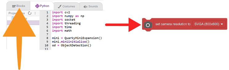
Using a different resolution may affect the camera feed, lane detection window, and tracking accuracy.
Camera Feed is Glitching
If the camera feed is lagging, freezing, or glitching, check the connection method and network quality.
Try the following:
- Make sure Quarky Intellio is connected properly.
In this guide, this enables real-time camera streaming, AI processing, and interactive project control.
- Check whether the Wi-Fi connection is stable.
- Keep the robot and computer closer to the Wi-Fi router.
- Avoid using slow or unstable internet connections.
- Restart the connection and run the program again.
A weak connection can affect the live camera stream and reduce lane-following accuracy.
If the Camera Feed is Mirrored.
If the robot behaves opposite to the lane direction, check whether the camera feed is mirrored.
- After running the Quarky Intellio lane-follower robot program, open the camera stream window and observe the live feed from the Lane Follower Robot.
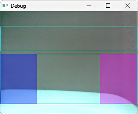
- Ensure that the feed direction matches the actual movement of the robot. If the feed is mirrored or reversed, the robot may make incorrect left and right corrections while following the lane.
Robot is Not Following the Lane Properly on the Arena
If the robot is unable to track the lane correctly on the arena, check the lighting and surface conditions.
Use the robot in an area with:
- Soft and even lighting
- No strong reflections
- No direct bright light on the lane
- No very dark shadows
- A clear contrast between the lane and the background
- A flat and non-reflective surface
Avoid glossy, reflective, very bright, or very dark areas because they can confuse the camera-based lane detection system.
Robot Still Does Not Follow the Lane Correctly
If the robot still has difficulty following the lane, adjust the tuning values in the Tuning Window.
Start by reducing the Base Speed.
A lower base speed gives the robot more time to detect the lane and make corrections smoothly.
Recommended tuning action:
- Reduce the Base Speed gradually.
- Observe the camera feed and lane detection window.
- Adjust values slowly instead of making large changes.
- Test again after each adjustment.
If the robot moves too fast, it may miss turns or leave the lane. Slowing it down usually improves tracking accuracy.
You can further improve the project by adjusting the tuning values, changing the lane layout, modifying the robot speed, or enabling additional object-detection behaviours.