Introduction
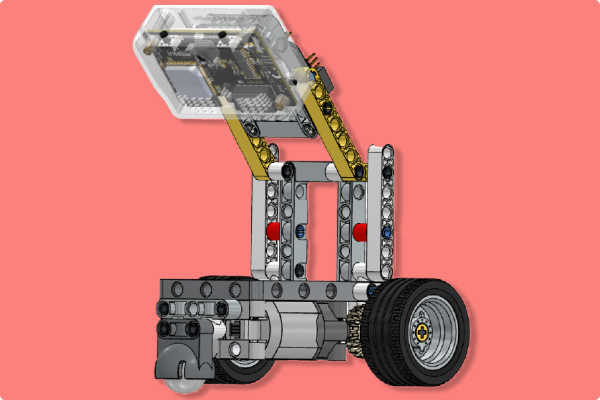
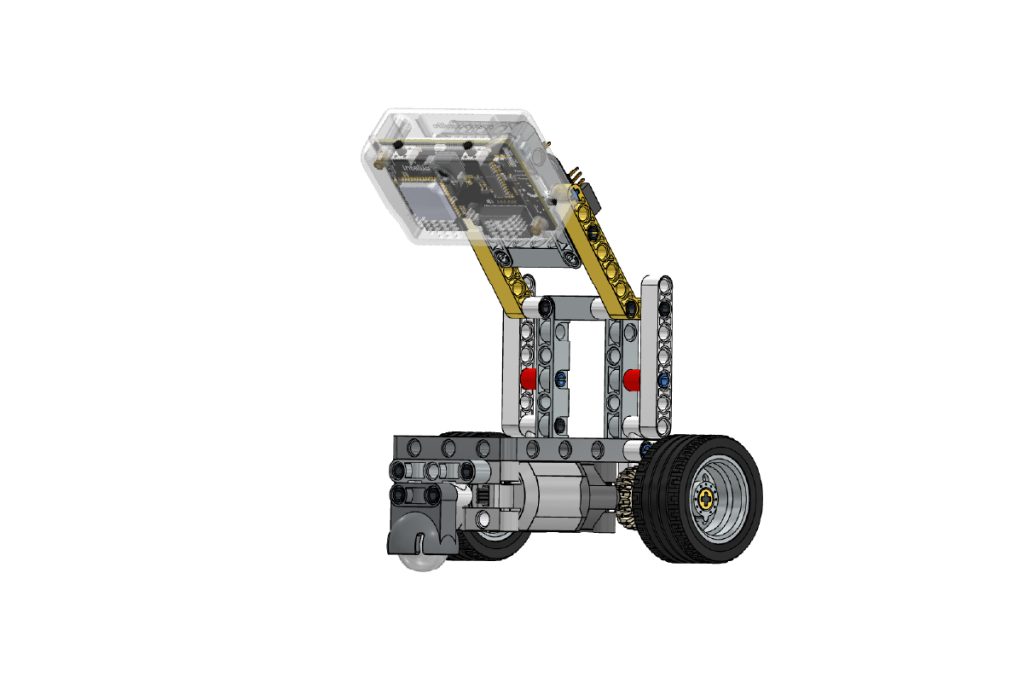
The Quarky Intellio Lane Follower Robot is a functional robotic model designed to demonstrate autonomous navigation using camera-based lane detection and motor-controlled movement.
Quarky Intellio processes visual feedback from its built-in camera and controls the motors’ speed and direction, allowing the robot to detect and follow a lane or a defined path. This project helps students understand robotics, artificial intelligence, computer vision, motor control, and autonomous navigation.
Please follow the step-by-step instructions below to construct the Lane Follower Robot.
Note: In each step, refer to the image for the exact orientation, alignment, and hole positions. The box in the top-right corner of each image shows the parts required for that step.
Step-by-Step Assembly Instructions
Step 1: Prepare the First Motor Sub-Assembly
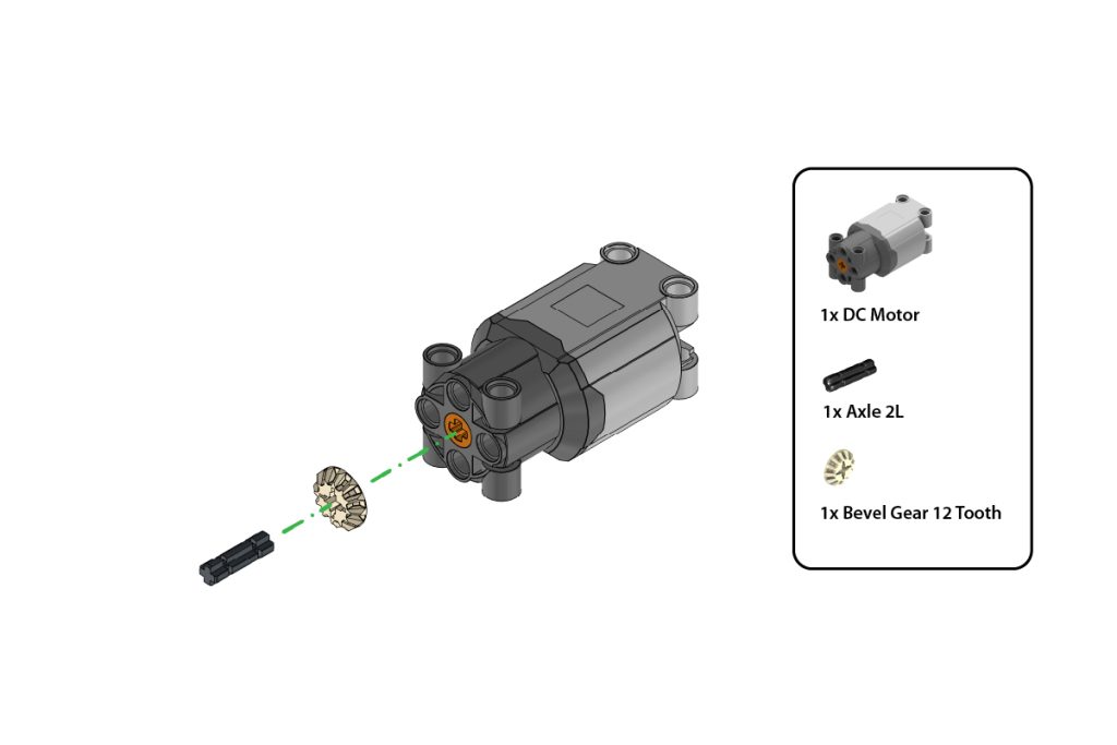
Take:
- one (1) DC Motor
- one (1) Axle 2L
- one (1) Bevel Gear 12 Tooth
Insert the Axle 2L into the shaft of the DC Motor. Attach the Bevel Gear 12 Tooth to the exposed end of the axle.
Press the gear firmly until it is securely fitted and aligned straight with the motor shaft, as shown in the image.
Step 2: Prepare the Second Motor Sub-Assembly
Repeat Step 1 to create a second identical motor sub-assembly.
Ensure both motor sub-assemblies have the same orientation and that both gears are fitted securely.
Step 3: Verify the Motor Sub-Assemblies
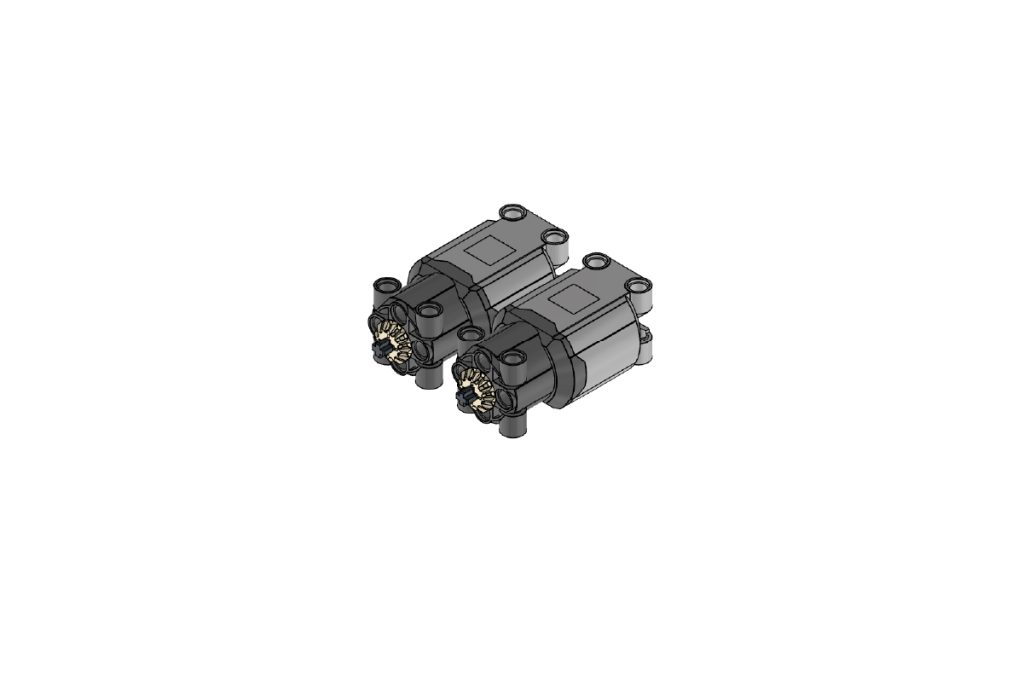
Place the two completed motor sub-assemblies side by side.
Confirm that:
- Both DC Motors are positioned in the same direction;
- Both Bevel Gear 12 Tooth parts are aligned correctly, and both motor sub-assemblies are identical.
Step 4: Mount the Motors on the Main Frame
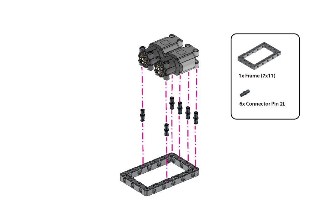
Take:
- one (1) Frame (7×11)
- Six (6) Connector Pin 2L (Black)
Insert the six Connector Pins 2L (Black) into the highlighted holes of the Frame (7×11).
Align the two motor sub-assemblies above the pins and press them firmly onto the frame.
Ensure both motors are securely fixed, evenly aligned, and positioned in the same direction, as shown in the image.
Step 5: Attach the Side T-Shape Beams
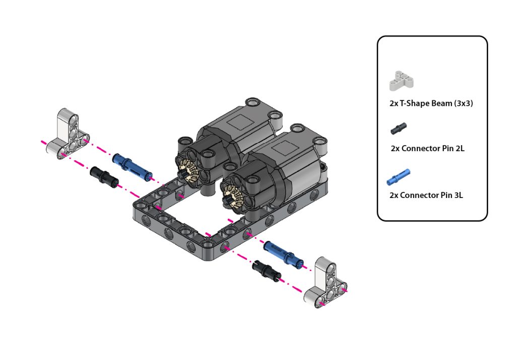
Take:
- two (2) T-Shape Beam (3×3)
- two (2) Connector Pin 2L (Black)
- two (2) Connector Pin 3L (Blue)
Insert one Connector Pin 2L (Black) and one Connector Pin 3L (Blue) into the highlighted side holes on each side of the Frame (7×11).
Attach one T-Shape Beam (3×3) to the exposed pins on the left side and the second T-Shape Beam (3×3) to the exposed pins on the right side.
Press both beams firmly and ensure they remain symmetrical.
Step 6: Complete the Front Support Structure
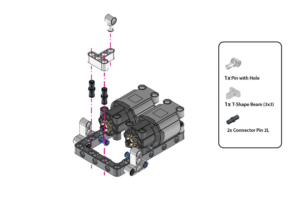
Take:
- one (1) Pin with Hole
- one (1) T-Shape Beam (3×3)
- two (2) Connector Pin 2L (Black)
Insert the Connector Pin 2L (Black) into the highlighted mounting holes.
Attach the one T-Shape Beams (3×3) in the orientation shown in the image.
Fit one Pin with Hole onto each T-shape beam. Ensure both supports are securely connected and aligned evenly on both sides.
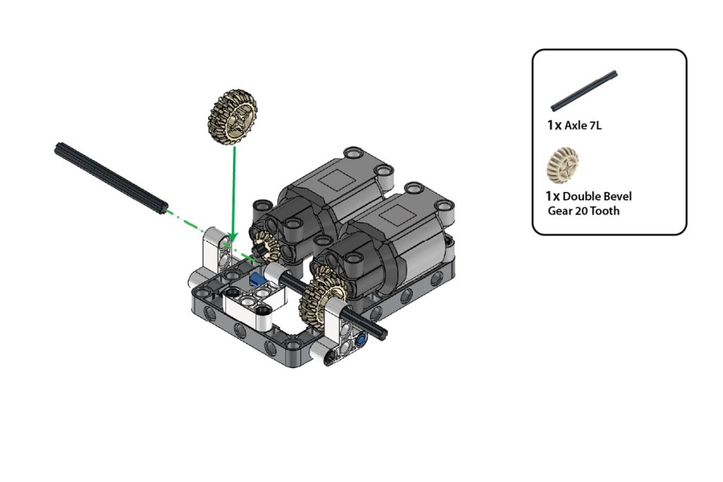
Step 7: Install the First Drive Axle and Gear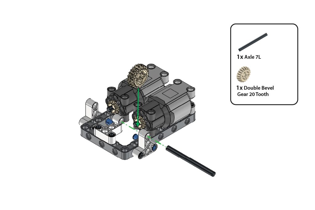
Take:
- one (1) Axle 7L
- one (1) Double Bevel Gear 20 Tooth
Insert the Axle 7L through the aligned holes of the first side support and motor assembly.
Slide the Double Bevel Gear 20 Tooth onto the axle and position it so that it meshes correctly with the Bevel Gear 12 Tooth attached to the motor.
Ensure the axle rotates freely and the gears engage smoothly.
Step 8: Install the Second Drive Axle and Gear
Take:
- one (1) Axle 7L
- one (1) Double Bevel Gear 20 Tooth
Repeat Step 7 on the opposite side of the chassis.
Insert the second Axle 7L through the aligned holes and attach the remaining Double Bevel Gear 20 Tooth.
Ensure both drive assemblies rotate smoothly and remain symmetrical.
Step 9: Attach the Cross Beam Support
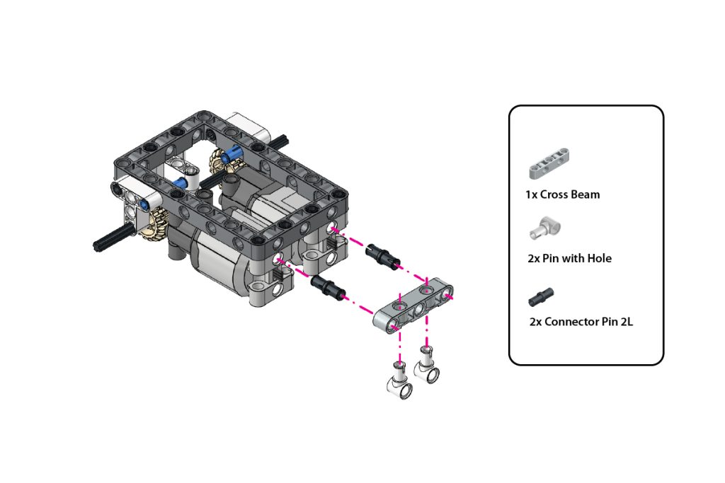
Take:
- one (1) Cross Beam
- two (2) Pin with Hole
- two (2) Connector Pin 2L (Black)
Insert the two Connector Pin 2L (Black) into the highlighted holes at the end of the Frame (7×11).
Align the Cross Beam with the exposed pins and press it firmly into place.
Insert the two Pin with Hole into the highlighted holes of the Cross Beam, with their circular holes facing downward, as shown in the image.
Step 10: Attach the Castor Wheel
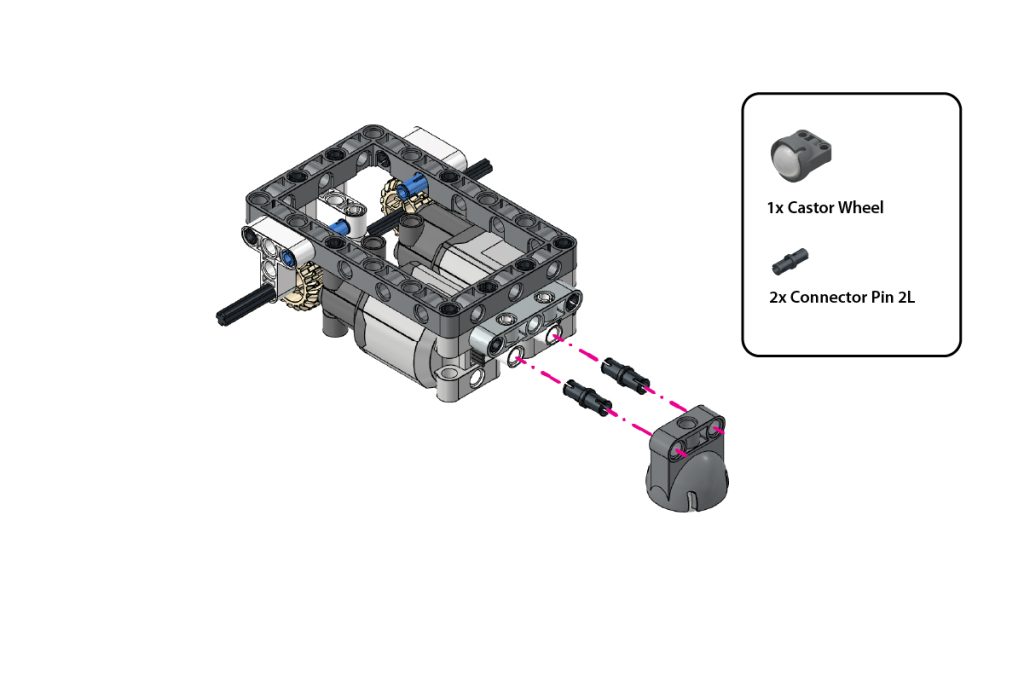
Take:
- one (1) Castor Wheel
- two (2) Connector Pin 2L (Black)
Insert the two Connector Pin 2L (Black) into the highlighted mounting holes of the Castor Wheel.
Align the Castor Wheel with the two Pin with Hole attached in the previous step.
Press the Castor Wheel firmly into place and ensure it is centred and able to rotate freely.
Step 11: Install the Drive Wheels
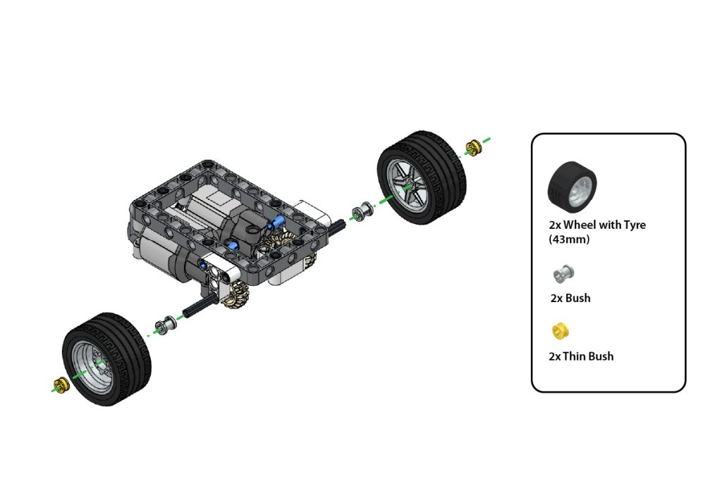
Take:
- two (2) Wheel with Tyre (43 mm)
- two (2) Bush
- two (2) Thin Bush
Slide one Bush onto each exposed Axle 7L.
Attach one Wheel with Tyre (43 mm) to each axle.
Secure each wheel by pressing one Thin Bush onto the outer end of the axle.
Ensure both wheels are firmly mounted but can rotate freely.
Step 12: Verify the Chassis Assembly
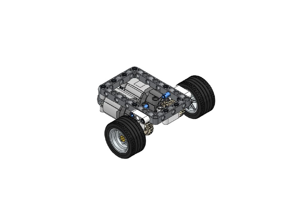
Check the completed chassis assembly.
Ensure that:
- Both drive wheels are aligned;
- The Castor Wheel rotates freely;
- Both motor gears mesh correctly;
- Both motors are securely attached, and
- The chassis remains level and stable.
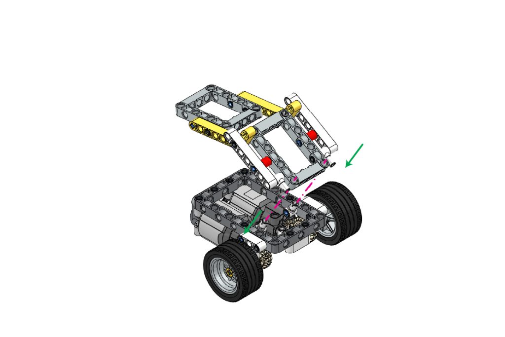
Step 13: Attach the Upper Mounting Pins
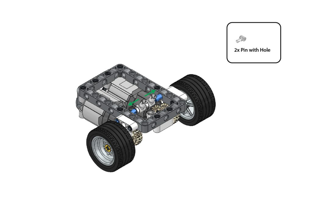
Take:
- two (2) Pin with Hole
Attach the two Pin with Hole to the exposed Connector Pin 3L (Blue) inside the chassis.
Position them in the direction shown by the arrows in the image.
Press both parts firmly and ensure they remain aligned, as these connections will support the upper frame assemblies.
Step 14: Prepare the First Upper Frame
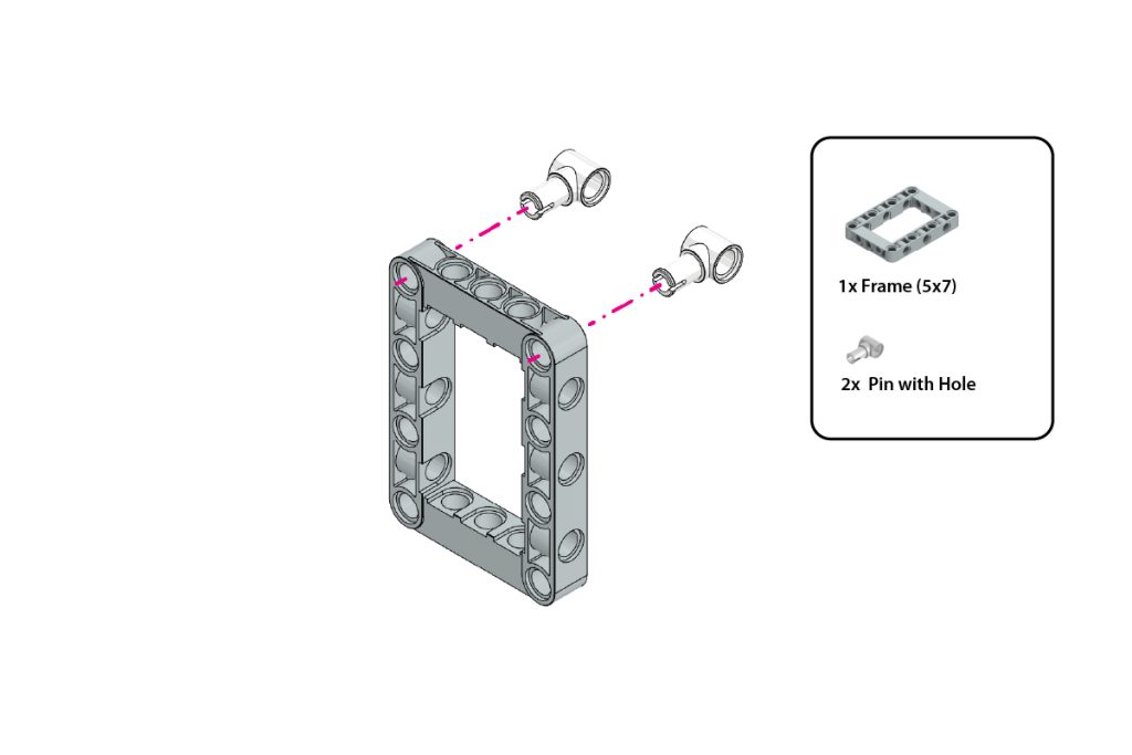
Take:
- one (1) Frame (5×7)
- two (2) Pin with Hole
Insert one Pin with Hole into each highlighted top corner hole of the Frame (5×7).
Ensure both Pin with Hole parts face outward and are positioned symmetrically, as shown in the image.
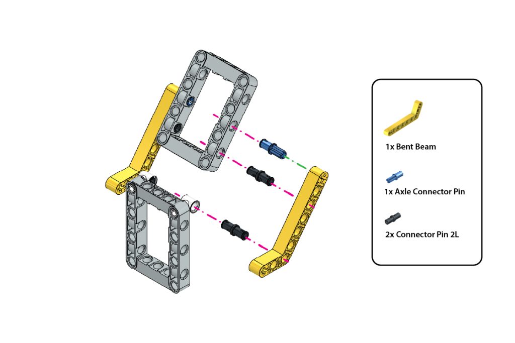
Step 15: Attach the Second Frame and First Bent Beam
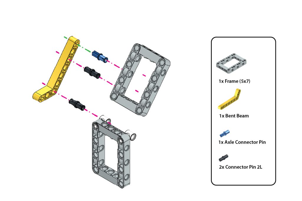
Take:
- one (1) Frame (5×7)
- one (1) Bent Beam
- one (1) Axle Connector Pin (Blue)
- two (2) Connector Pin 2L (Black)
Position the second Frame (5×7) above the frame prepared in Step 14.
Insert the Axle Connector Pin (Blue) and two Connector Pin 2L (Black) into the highlighted holes of the Bent Beam.
Align the pins with the corresponding holes of both frames and press them firmly into place.
Maintain the exact angle and orientation shown in the image.
Step 16: Attach the Second Bent Beam
Take:
- one (1) Bent Beam
- one (1) Axle Connector Pin (Blue)
- two (2) Connector Pin 2L (Black)
Repeat the previous step on the opposite side of the upper-frame assembly.
Attach the second Bent Beam using the Axle Connector Pin (Blue) and two Connector Pin 2L (Black).
Ensure both Bent Beams are positioned symmetrically and support the upper Frame evenly.
Step 17: Attach the First Vertical Beam
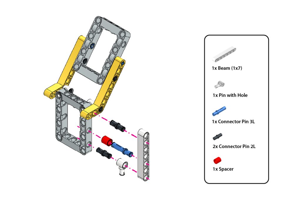
Take:
- one (1) Beam (1×7)
- one (1) Pin with Hole
- one (1) Connector Pin 3L (Blue)
- two (2) Connector Pin 2L (Black)
- one (1) Spacer
Insert the Pin with Hole into the bottom hole of the Beam (1×7).
Slide the Spacer onto the Connector Pin 3L (Blue).
Insert the Connector Pin 3L with the Spacer into the highlighted middle hole of the Beam.
Insert the two Connector Pin 2L (Black) into the remaining highlighted holes.
Align the Beam with the corresponding holes on one side of the upper-frame assembly and press all connections firmly into place.
Step 18: Attach the Second Vertical Beam
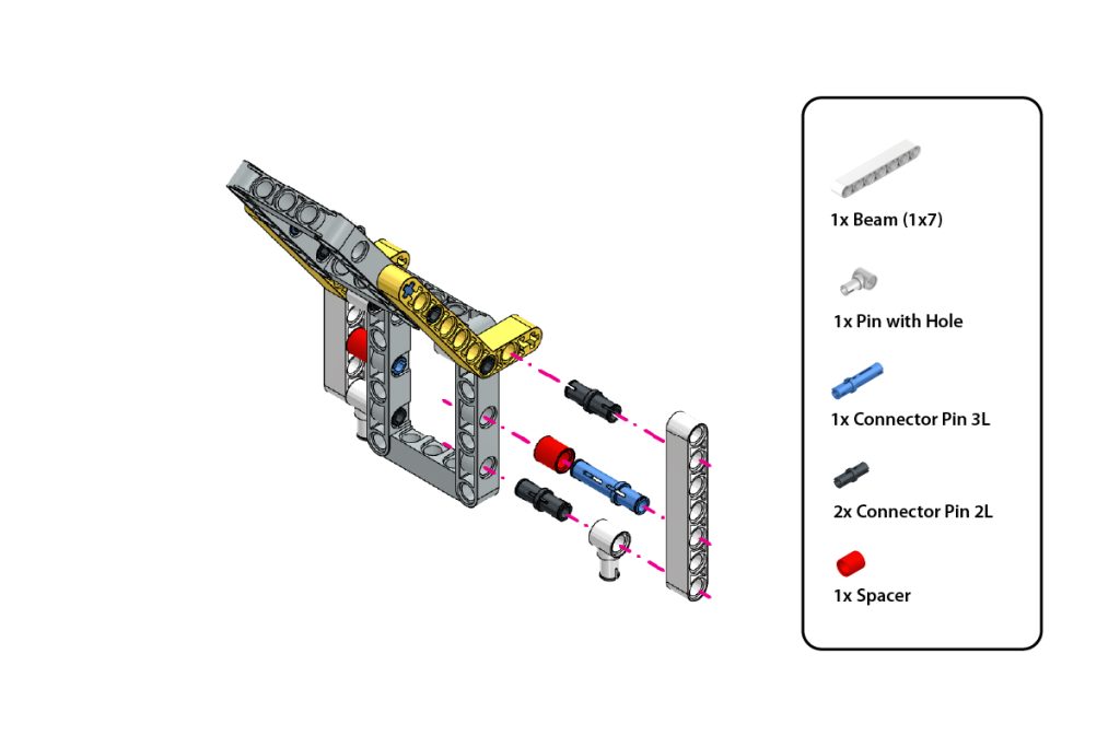
Take:
- one (1) Beam (1×7)
- one (1) Pin with Hole
- one (1) Connector Pin 3L (Blue)
- two (2) Connector Pin 2L (Black)
- one (1) Spacer
Repeat Step 17 on the opposite side of the upper-frame assembly.
Ensure both Beam (1×7) parts are attached symmetrically and that the Pin with Hole connections face downward, as shown in the image.
Step 19: Repeat the Upper-Frame Assembly on the Opposite Side
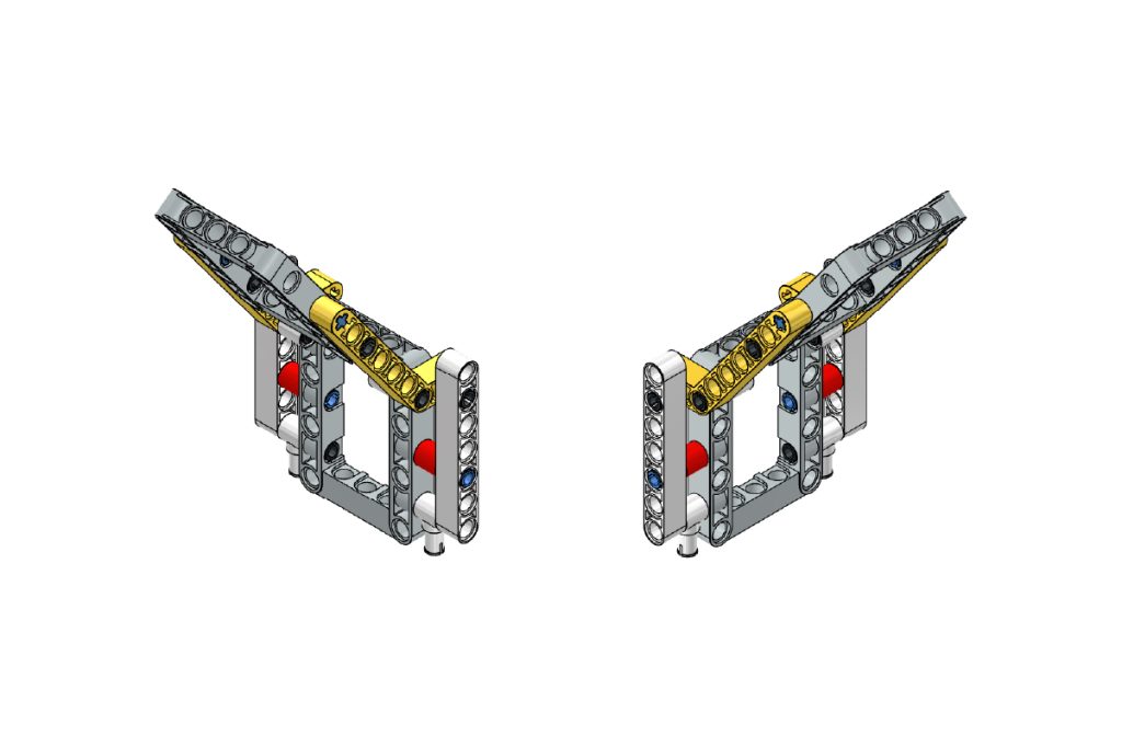
Using the remaining components, repeat Steps 15–18 on the opposite side to create a matching upper-frame structure.
Ensure that:
- Both Bent Beams are mounted in the same orientation as shown in the image.
- Both Beam (1×7) assemblies are positioned symmetrically.
- All Pin with Hole connections face in the correct direction.
- The Spacer and Connector Pins are installed in the same positions on both sides.
- Both upper-frame structures are aligned evenly and maintain the same angle.
After completing this step, the upper-frame assembly should appear symmetrical on both sides and match the configuration shown in the image.
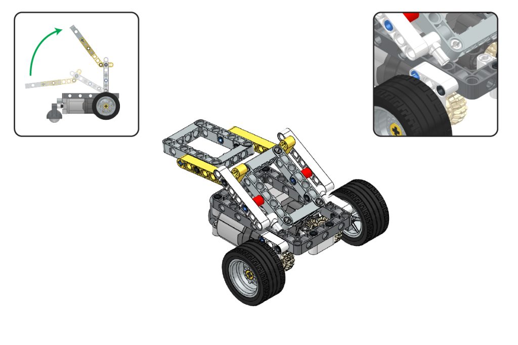
Step 20: Mount the Upper Frames on the Chassis
Take the two completed upper-frame sub-assemblies and position them above the chassis.
Align the lower Pin with Hole connections of the upper frames with the mounting points prepared on the chassis.
Lower the upper-frame assemblies carefully and press them firmly into place.
Ensure that:
- Both upper frames are securely attached;
- Both sides are symmetrically aligned;
- The frames maintain the angle shown in the image, and
- The joints move smoothly without obstruction.
Step 21: Attach the Mini Expansion Board
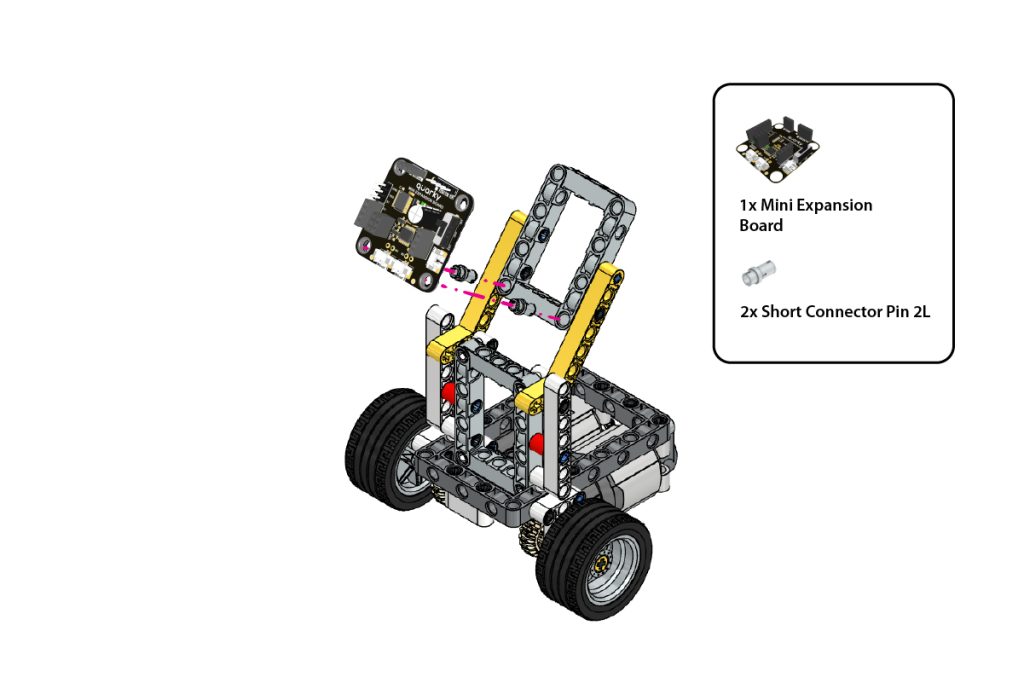
Take:
- one (1) Quarky Mini Expansion Board
- two (2) Short Connector Pin
Place the Quarky Mini Expansion Board on the designated upper-frame mounting area.
Align its mounting holes with the highlighted holes on the frame.
Insert one Short Connector Pin into each mounting point and press firmly until the board is securely fixed, remains level, and matches the required orientation.
Step 22: Attach Quarky Intellio
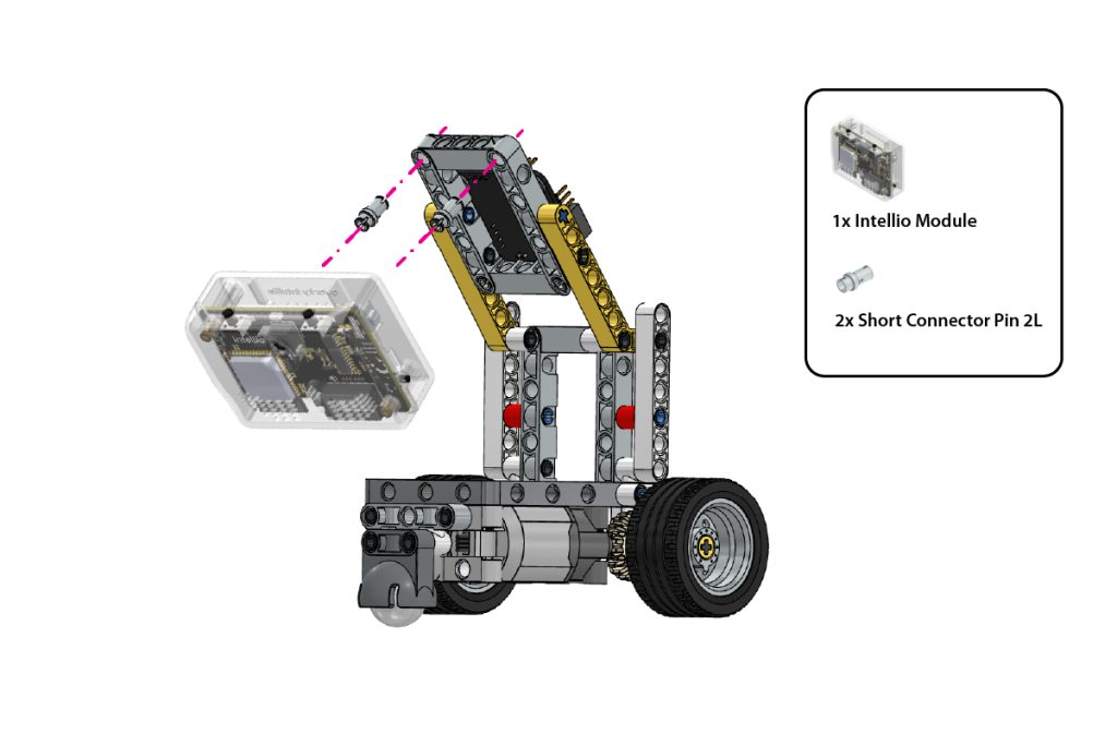
Take:
- one (1) Quarky Intellio
- two (2) Short Connector Pin
Position Quarky Intellio on the remaining upper-frame mounting area.
Align the mounting holes of Quarky Intellio with the corresponding holes on the frame.
Insert the two Short Connector Pin and press them firmly until Quarky Intellio is securely mounted.
Ensure its camera faces forward and remains unobstructed.
Step 23: Verify the Final Assembly
Check the completed Lane Follower Robot.
Ensure that:
- Quarky Intellio is securely mounted;
- The Mini Expansion Board is fixed firmly;
- The camera faces forward at the correct angle;
- Both upper frames are symmetrical;
- The wheels and gears rotate smoothly;
- The Castor Wheel moves freely, and
- There are no loose beams, pins, or connectors.
The mechanical assembly of the Quarky Intellio Lane Follower Robot is now complete.
Connect the Electronics and Set Up the Lane Follower Program
After completing the mechanical assembly, connect Quarky Intellio, the Mini Expansion Board, and both DC Motors. Then open the provided Lane Follower program in PictoBlox, install the required Python packages, configure the network settings, and run the robot.
Step 24: Connect Quarky Intellio to the Mini Expansion Board
Connect Quarky Intellio to the Mini Expansion Board according to the wiring diagram.
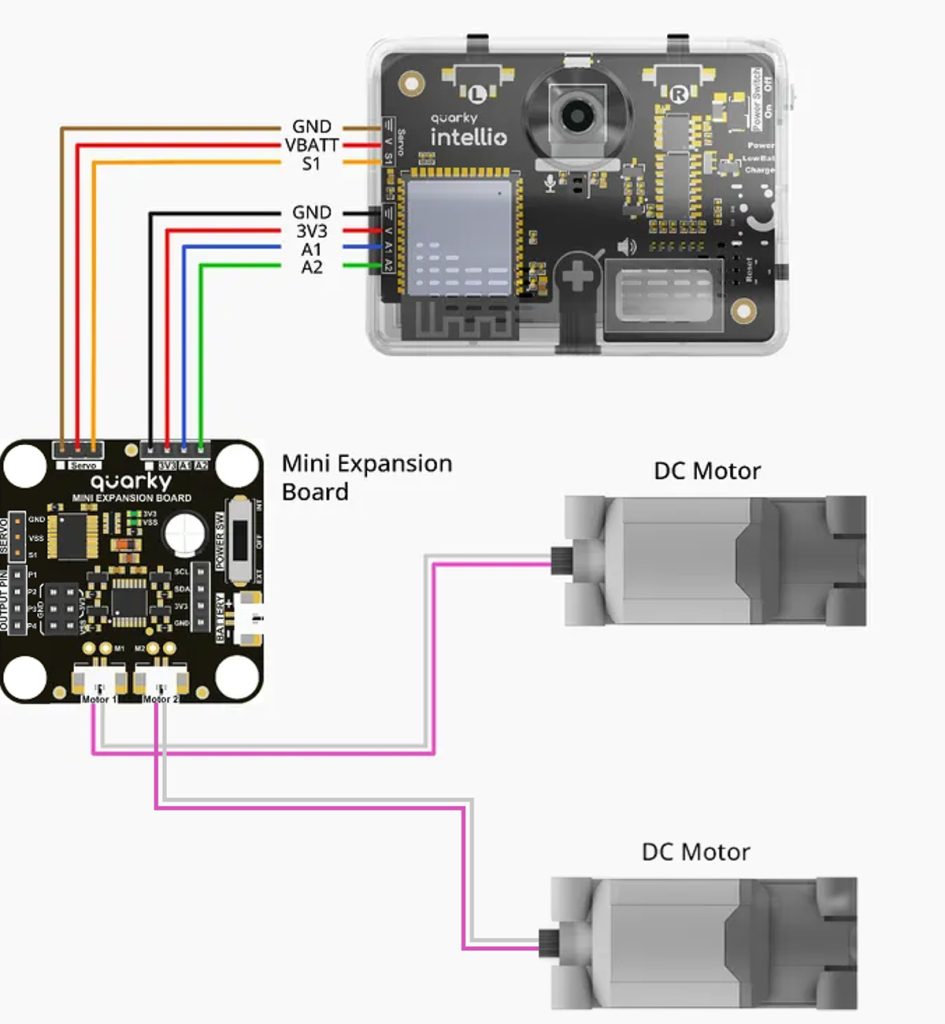
Ensure that every wire is connected to the matching labelled pin and follows the same orientation shown in the wiring diagram.
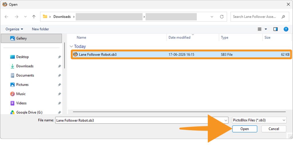
Step 25: Download the Lane Follower Program
Download the provided Lane Follower Robot Python project file and save it in an easily accessible folder on your computer.
Remember the saved location, as you will need to open the file in PictoBlox.
Step 26: Open the Program in PictoBlox
- Open PictoBlox and choose Blocks or Py Editor.
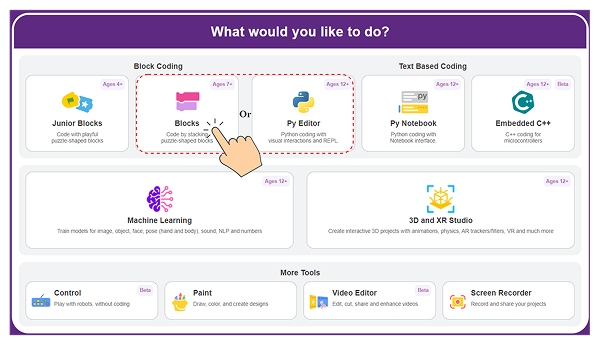
- Use the Open option to browse to the downloaded Lane Follower project file, select the file and open it.

- Confirm that the complete Python program appears in the editor.
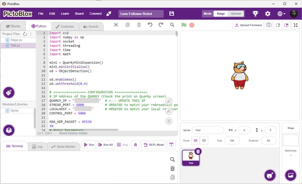
Do not use Block Coding for this example because the Lane Follower program is written in Python.
Step 27: Connect Quarky Intellio to PictoBlox
Connect Quarky Intellio to PictoBlox using a Quarky Intellio Wi-Fi connection method.
Once the connection is established successfully, copy the IP address assigned to Quarky Intellio.
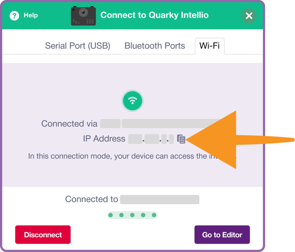
This IP address will be required in the Python program for communication between PictoBlox and Quarky Intellio.
Update the following line in the code with your connected Quarky Intellio IP address:
QUARKY_IP = "***.***.*.**" # <--- UPDATE THIS IPMake sure the IP address in the code exactly matches the IP address displayed after connecting to Quarky Intellio.
Step 28: Install the Required Python Packages
The Lane Follower program uses external Python libraries for image processing, networking, and numerical calculations. Before running the program, ensure that all required dependencies are installed.
The program uses the following libraries:
import cv2
import numpy as np
import socket
import threading
import time
import math
If any of these dependencies are not already installed on your system, install them using the Install Pip Package option in PictoBlox.
- Open the Install Pip Package option in PictoBlox.
- Enter the name of the package you want to install, then click Install to begin the installation process.

The following packages may need installation:
- opencv-python (for cv2)
- numpy
The remaining libraries (socket, threading, time, and math) are included with Python by default and do not require separate installation.
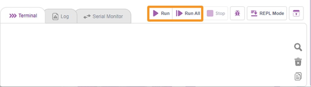
Step 29: Run the Program.
Once Quarky Intellio is connected and all required packages are installed, run the Python script.
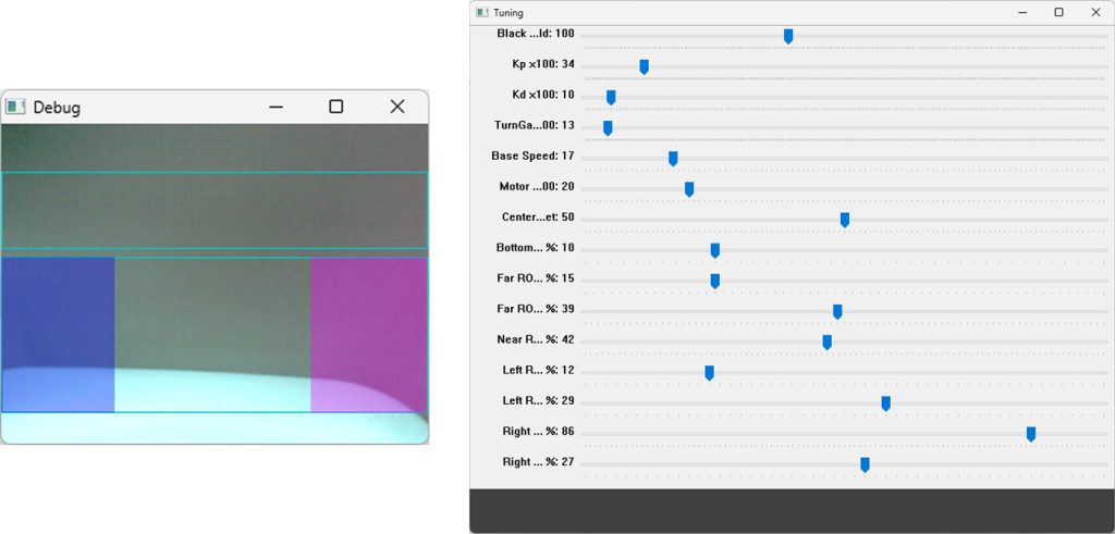
 The program will open a Tuning Window containing adjustable parameters for lane detection and robot movement.
The size and appearance of the detected lane region may vary depending on:
- The width of the lane
- The distance of the robot from the lane
- Camera positioning
- Lighting conditions
- Arena design
You can adjust parameters such as:
- Black Threshold
- Kp
- Kd
- Base Speed
- Turn Gain
- Region of Interest (ROI)
These settings help the robot accurately identify and follow different lane sizes and track layouts. If the robot is unable to follow the lane correctly, adjust these values gradually while observing the camera feed and lane-detection windows.
The tuning parameters may need to be modified whenever a different arena, lane width, or lighting condition is used.
Step 30: Prepare the Lane
Place the robot on a lane-following arena with clearly visible dark lane boundaries on a light background.
Ensure that:
- The surface is flat;
- The lane is well lit;
- Shadows do not cover the lane;
- The camera has a clear forward view;
- The wheels can rotate freely, and
- The robot has enough space to move safely.
Run the Program.
Run the Python program in PictoBlox.
The Quarky Intellio Lane Follower Robot is now ready for testing and experimentation.
You can further improve the project by adjusting the tuning values, changing the lane layout, modifying the robot speed, or enabling additional object-detection behaviours.