A servo motor, or simply a servo, is a device used to rotate or push parts of a machine with precision. Unlike a standard DC motor that spins continuously, a servo rotates to a specific angle and then holds that position until a new instruction is given.
This precise, controllable movement makes servo motors essential in robotics. They are used in robot joints, steering mechanisms, camera mounts, gripper arms, and walking robots, in any application where exact positioning matters.
What’s inside a Servo Motor?
If you were to open a servo motor, you would find four key components working together:
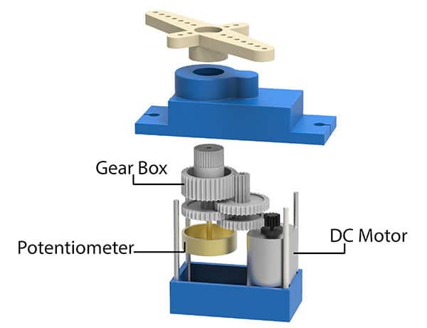
- A DC Motor: The actual source of rotational movement. It spins fast but with low torque on its own.
- A Potentiometer: A small sensor connected to the output shaft. It continuously measures the current angle of the shaft and sends that information back to the control circuit. This is what allows the servo to know exactly where it is positioned at all times.
- A Gear Train: A series of interlocked gears that slow down the DC motor’s high-speed rotation and convert it into the precise, controlled movement needed for robotics. The gear train is why a servo can hold a position firmly even under load.
- A Control Circuit: The brain of the servo. It receives an angle command, reads the current position from the potentiometer, and drives the DC motor to close the gap between the shaft’s current position and its desired position. Once the target angle is reached, it holds that position.
Together, these four components make the servo motor one of the most reliable and widely used actuators in robotics, electronics, and automation.
Servo Calibration
The purpose of Servo Motor Calibration is to ensure the servo shaft is positioned at the correct starting angle before use in a project. In Quarky Intellio-based builds, such as the Intellio Rover or any servo-driven mechanism, the servo must be at its neutral position (90°) before mechanical parts like steering arms or beams are attached.
Calibrating the servo motors before assembly prevents misalignment that would otherwise require full disassembly to fix.
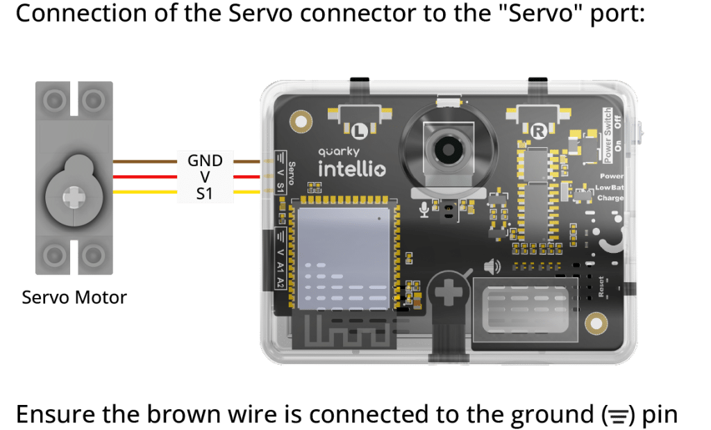
Connecting the Servo to Quarky Intellio
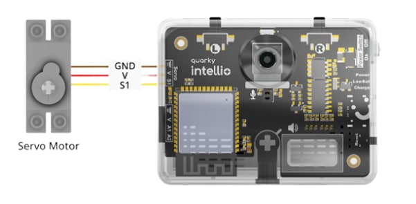
Step 1: Take the 180° Servo Motor and connect it to one of the Servo Connector ports on the left side of the Quarky Intellio board.
Important: When plugging in the servo connector, always make sure the brown wire is on your left side. The brown wire is the ‘ground wire’. Inserting it in the wrong orientation can damage the servo motor or the Quarky Intellio board.
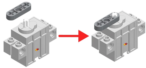
Step 2: Once connected, insert a Thin Beam(1×3) into the servo shaft. This beam serves as a visible indicator arm that helps you confirm the servo’s direction and angle during calibration.
Understanding Servo Angles
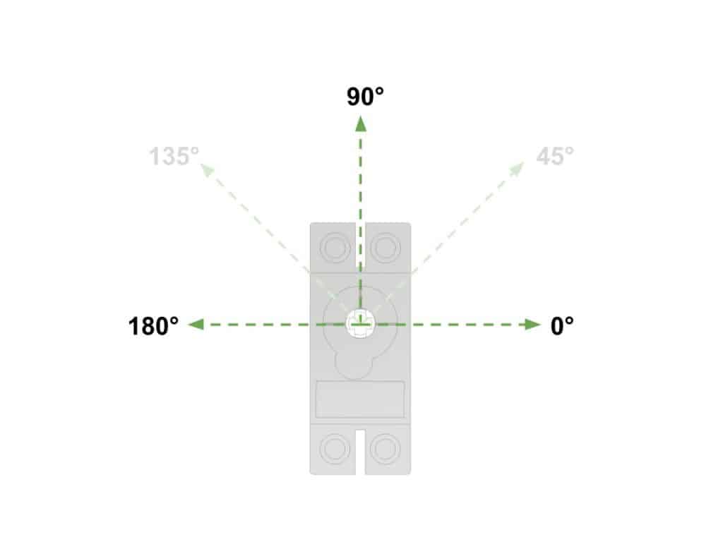
Before calibrating, it is important to understand how servo angles work. The Quarky Intellio servo uses a 0° to 180° range. The three key positions are:
| Angle | Direction Description | Meaning |
| 0° | Far Right | Maximum rotation to the right |
| 45° | Right | 45 degrees to the right of forward |
| 90° | Forward / Neutral | Straight ahead, this is the calibration target |
| 135° | Left | 45 degrees to the left of forward |
| 180° | Far Left | Maximum rotation to the left |
The calibration target is always 90°. This is the neutral position from which all other movements are referenced. Attaching mechanical parts before the servo is at 90° will cause the robot’s range of motion to be off-centre.
Servo Control Block in PictoBlox
PictoBlox provides one primary block for controlling servo motors with Quarky Intellio:
Block:
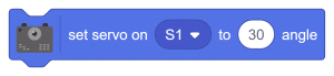
This block sets the servo connected to the selected port to any angle between 0° and 180°. The port selector (S1, S2, etc.) corresponds to the physical servo connector port on the Quarky Intellio board. The angle value in the round input field is the target position the servo should move to.
Calibrating the Servo (Step-by-Step)
Follow these steps to calibrate your servo motor to the correct neutral position using PictoBlox.
Step 1: Open PictoBlox on your device. If PictoBlox is not installed, download the latest version from: Download PictoBlox.

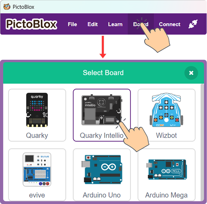
Step 2: Select Quarky Intellio as the board from the Board menu in the toolbar.
Step 3: Connect your Quarky Intellio to PictoBlox via the Quarky Intellio Connection Guide.
Follow the step-by-step instructions in the Quarky Intellio connection guide to establish the connection.

Step 4: In the Block Coding environment, go to the Events category in the Block Palette. Drag the “when Green Flag clicked” block into the scripting area.

Step 5: Go to the Quarky Intellio or Robot category in the Block Palette. Find the “set servo on S1 to ( ) angle” block and place it directly below the “when Green Flag clicked” block.
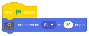
Step 6: Change the angle value in the block from its default to 90.

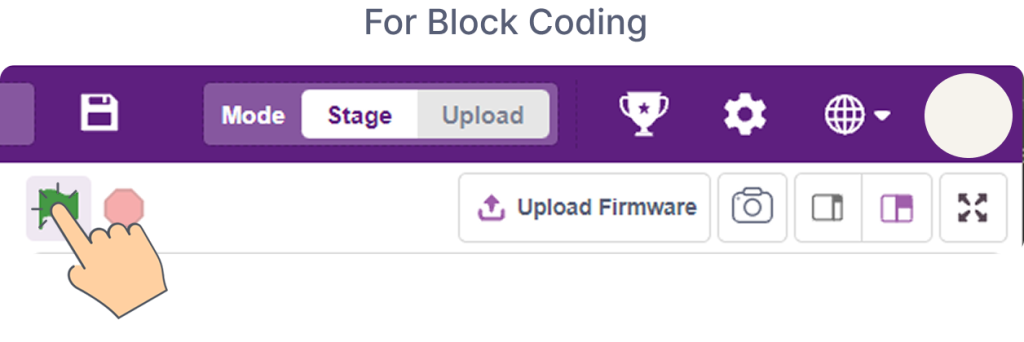
Step 7: Click the Green Flag button in the stage area to run the script.
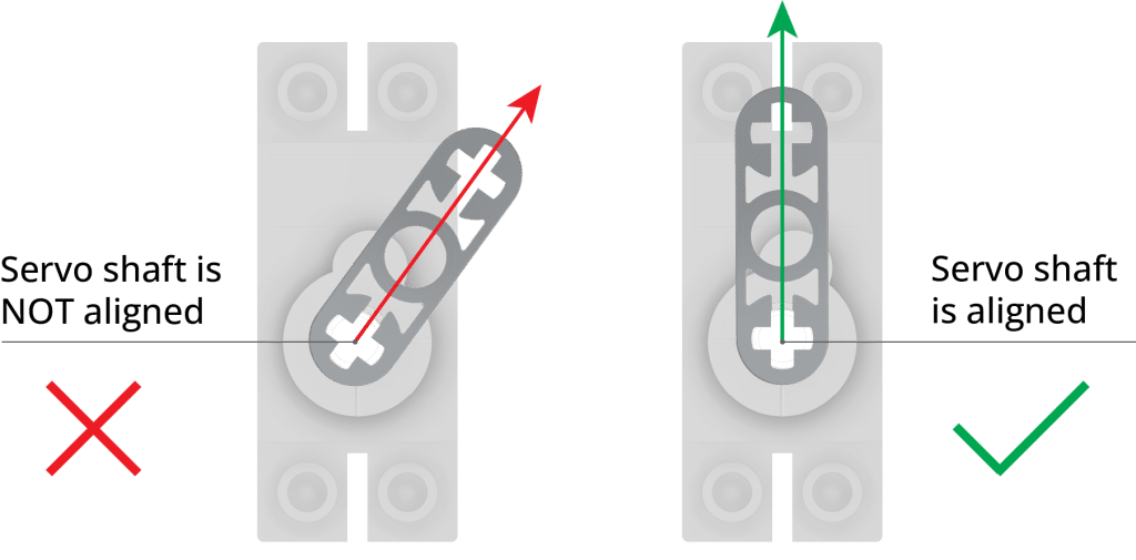
Step 8: The servo shaft will move to 90° in the forward/neutral position. Watch the Thin Beam(1×3) on the shaft. It should now be pointing straight forward.
Note: There is a chance the servo is already at 90° by default when connected. In that case, temporarily change the angle to 30° or 45°, run the script to confirm movement, and then change it back to 90° and run it again to set the neutral position. The Thin Beam(1×3) is only used during calibration. Once calibration is complete, remove it before proceeding with the assembly steps for your project.
Activity: Servo Movement at Multiple Angles
Now that the servo is calibrated, explore its full range of movement using a simple multi-angle programme.
Code:
Testing:
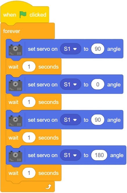
When you click the Green Flag, the servo will rotate through the full range of positions, far right (0°), forward neutral (90°), far left (180°), pausing at each position for one second before moving to the next.
Watch the Thin Beam(1×3) on the shaft as it moves through each position. This provides a clear, physical understanding of what each angle value means in real space, which is exactly the understanding you need to program servo-based mechanisms correctly in any project.
Try changing the angle values and the wait times. Observe how the servo responds to different inputs and how smoothly or quickly it transitions between positions.
Conclusion
Calibration is a small step, but it is a critical one. A servo that starts at the wrong position causes every mechanical component attached to it to be misaligned. Getting this right first means every project built on top of it, the Intellio Rover, a walking robot, a steering mechanism, or a camera mount, starts from a reliable, known position.
Know more
Frequently Asked Questions
1. Why must the brown wire always be on the left?
The brown wire is the ground wire of the servo connector. Inserting it in the wrong orientation reverses the polarity on the servo’s power line, which can damage the servo motor, the Quarky Intellio board, or both. Always check wire orientation before powering on.
2. What if my servo does not move when I run the calibration script?
First, check that Quarky Intellio is connected to PictoBlox and shows a green Connected indicator. Then confirm the servo cable is fully inserted into the servo port. If the servo was already at 90° before the script ran, it will not make any visible movement try setting the angle to 30° first to confirm it responds.
3. Why do I attach the Thin Beam(1×3) before calibrating?
The Thin Beam(1×3) provides a visible reference point on the servo shaft. Without it, it is difficult to see whether the shaft is at exactly 90° just by looking at the servo body. The beam makes the angle physically visible so you can confirm the neutral position before attaching any structural parts.
4. Can I calibrate to an angle other than 90°?
For most Quarky Intellio projects, particularly the Rover, the assembly steps are designed around the servo being at 90° before mechanical parts are attached. Calibrating to a different angle before assembly will cause all subsequent movements to be off-centre. Always use a 90° position as the calibration target unless specific project documentation states otherwise.
5. What is the full range of the servo motor?
The servo operates from 0° (maximum rotation to the right) to 180° (maximum rotation to the left), with 90° as the centred neutral position. The “set servo on S1 to angle” block in PictoBlox accepts any whole number value within this range.
6. Do I remove the Thin Beam(1×3) after calibration?
Yes. The Thin Beam(1×3) is only used during calibration as a visual reference. Once you have confirmed the servo is at 90°, remove the beam before proceeding with the assembly steps for your specific project.
7. Which PictoBlox version do I need?
PictoBlox version 9.1.0 or later is required for full Quarky Intellio support. Download the latest version from: Download PictoBlox.